YesAX V3.1.2 - Software User Manual - 第172页
12 -6 Other X-Ray Inspection Features 12.2.3 Interacting w ith 3D Rendering Win dow The 3D Rendering function allows you to interact with the rendered surface using the keyboard and the mouse. Rotate : To rotate the surf…

Other X-Ray Inspection Features 12-5
12.2.2 Using 3D Rendering Dialog
The 3D Rendering dialog contains the settings that control how the surface is rendered and
displayed. All the settings, as well as the positions and sizes of the image ROI and the 3D
Rendering window, will persist after the function or program exits.
Resolution: The Resolution value ranges from 1 to 10. It controls how many pixel samples from
the image ROI are used to render the 3D surface.
The higher the resolution, the more pixels are used. The more pixels used, the more accurately
the rendered surface reflects the original image data variation within the ROI and the more time
and memory space it takes to do the rendering.
Height: The Height value ranges from 1 to 10. It changes the height of the rendered surface. The
higher the value, the more stretched the surface appears along the Z axis.
X-ray Image: This is a flag that tells the function how to interpret the image data. When this flag
is checked, the image is assumed to be an X-ray image. For an X-ray image, we are more
interested in dark areas, so the darker areas in the image correspond to higher areas on the
rendered surface. Because this software mostly deals with X-ray images, this flag should usually
be left checked. If the flag were unchecked, the rendered surface would turn upside down,
because the bright areas would stand out.
Bottom Image: When this flag is checked, the original image area in the ROI is drawn under the
rendered surface. It makes it somewhat easier for the user to visualize the relation between the
image ROI and the rendered surface.
Color Map: When this option is selected, the rendered surface is drawn with pseudo-coloring.
Eight colors are used to paint the surface areas at different levels of height. There are 256 levels
of height (because there are 256 image gray levels). Each color represents 32 consecutive levels.
For instance, the areas that take the lowest 32 levels are painted with violet; the areas that take
the highest 32 levels are painted with magenta.
Single Color: When this option is selected, the rendered surface is painted with only one color—
green.
Image Texture: When this option is selected, the original image in the ROI is directly mapped
onto the rendered surface. The surface appears covered by the image in the ROI.
Wireframe: When this flag is checked, the surface is rendered as meshes of quadrilateral outlines,
instead of a filled surface. To see the wire frame more clearly, lower the rendering resolution or
increase the size of the 3D Rendering window. Otherwise, the meshes appear too dense.
Opacity: The Opacity value ranges from 0 to 255. It changes the opacity of the rendered surface.
When the value is 255, the surface is completely opaque. When the value is between 0 and 255,
the surface is translucent in varying degree. When the value is lowered to 0, the surface becomes
completely transparent and thus invisible.
Z Cutout: The Z Cutout value ranges from 0 to 255. It tells the function not to display some
surface areas, depending on the height level. When it is X (X is a value between 0 and 255), the
areas with a height level lower than X will not be displayed. The lower part looks like being cut
out. When the value is 0, the whole surface is shown. The higher the value, the more the lower
part is cut out.

12-6 Other X-Ray Inspection Features
12.2.3 Interacting with 3D Rendering Window
The 3D Rendering function allows you to interact with the rendered surface using the keyboard
and the mouse.
Rotate: To rotate the surface about the Z axis (the blue axis), press the left arrow key (rotate
clockwise) or the right arrow key (rotate counterclockwise). Press and hold the key to let the
surface rotate continuously. To rotate the surface about the horizontal axis, that is parallel to the
screen, use the up and down arrow keys.
You may also use the mouse to rotate the surface. To rotate about the Z axis, click the left button
in the 3D Rendering window and drag it to the left (rotate clockwise) or to the right (rotate
counterclockwise). To rotate about the horizontal axis, drag the mouse in the up or down
direction.
Zoom In/Out: To make the surface appear larger (zoom in), press the + key. To make the surface
appear smaller (zoom out), press the – key.
NOTE
Use the + and – keys on the number key pad located on the right side of the
keyboard.
12.3 Annotation & Notes
Components on the circuit board such as resistors, capacitors, and ICs are collectively called
parts. The inspection recipe organizes information based on the concept of parts. Because of the
one to one correspondence with the parts and the “parts” on the circuit board it is an easy concept
to understand. A part can have any number of the three types of inspection: Mark, Lead Bank
and Solder.
12.3.1 Annotation command
The Annotation command allows you to annotate the image in the current image window with
text. Upon entry, the Text Entry dialog box appears in the window. Type in any text within the
text entry field in the dialog box. Characters typed in the Test Entry dialog box are
simultaneously displayed at the upper left corner of the image window. The text can be edited
with any editing keys on the keyboard such as Backspace, Delete, Insert, Home, End, arrow keys,
etc.
Press the OK button to exit the Text Entry function and accept the text or press the Cancel
button to discard the text.
After entering the text and closing the dialog box, you can reposition the text to anywhere on the
image. To do this, place the mouse cursor on the text at the upper left corner. Click and drag the
mouse cursor to the desired position and release the left mouse button. While the mouse cursor is
moving, a rectangle of the size of the text will follow the moving cursor. When the left mouse
button is released, the text will be drawn at the new position of the rectangle.
Use the Edit or Delete function to change or delete the text at any time. Right click on the
annotation to open the Annotation pop-up. Select Font to customize the color, font and
background of the text.
Other X-Ray Inspection Features 12-7
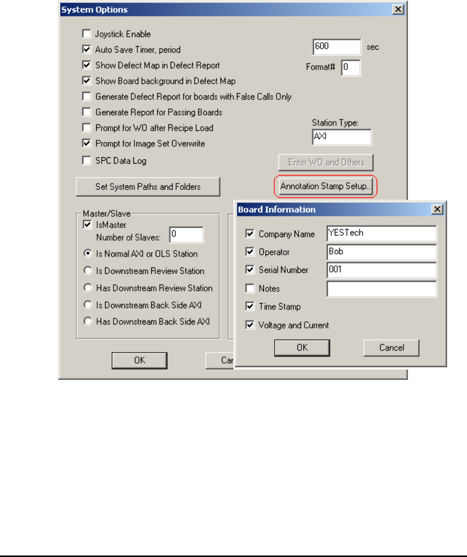
12.3.2 Annotation Stamp command
The Annotation Stamp command provides the ability to stamp the image in the current image
window with your pre-defined information. This information could include Company name,
Operator, Serial number, Notes, Time stamp, or X-ray voltage and current. This information is
overlaid on the upper left corner of the image. You can then reposition it using the mouse. See
the Annotation command (12.3.1) for details of repositioning.
Select Systems Options>Annotation Stamp Setup… The Board Information dialog opens.
Select any item to enable or disable and also edit the contents for each item, except for the Time
Stamp and Voltage and Current information. These two are assigned by the software
automatically, according to the current setup.
The stamp can be deleted using the Delete function in the pop-up menu. The text color, font and
style used in the stamp are the same as the text used in the Annotation command and can be
customized using the Font sub-menu. Please see those functions for details.