YesAX V3.1.2 - Software User Manual - 第186页
13 -8 Part List and Part Libra ries On the Package Lib page it is possible to select multiple package s using a combination of the mouse and the Shift- Ctrl keys. The Yes AX software ships with one Standard Packag e Libr…
Part List and Part Libraries 13-7
With recipe specifics stored in the central library, it is also possible to create new recipes from
the information stored in the central library. This feature is useful when you propagate a group of
recipes onto a new AXI machine. Press the Create New Recipe from Central Lib. button to
launch a dialog listing the available recipes stored on the central library. Select one or more
recipes to create.
Inside the central library folder part data is saved in a text file with the “.part” extension.
Appendix B Sample Central Library .part file shows a sample “.part” file.
Recipes with both local and central libraries have the best of both worlds; the flexibility offered
by the local library plus the convenience offered by the central library.
13.4.1 YesCLM
The Central Library is a very useful feature on Nordson YESTECH’s AXI machines, especially
in a high-mix production environment where many AXI recipes need to be created and managed.
YesCLM is the secondary central library management software for Nordson YESTECH’s AXI
machines. Central libraries can be managed using the YesAX software, so YesCLM is not
absolutely needed for using the central library feature. However, YesCLM makes managing
central libraries a lot easier. This is especially true for environments with multiple AXI machines
sharing multiple central libraries. The YesCLM software is provided to all Nordson YESTECH
AXI customers at no additional charge. Please refer to the document on YesCLM (YesCLM.doc)
in the document folder on the release CD.
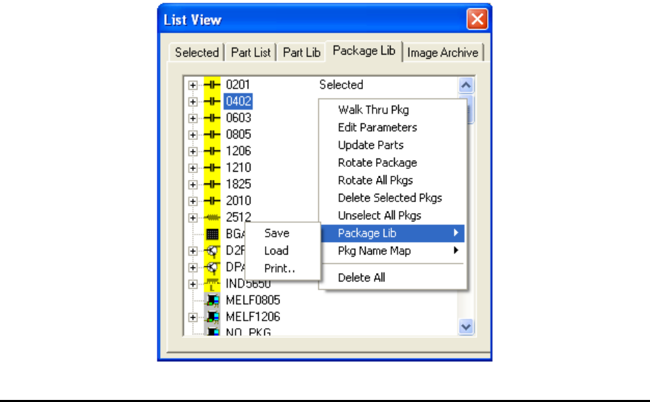
13.5 Package Library
The package of a part contains attributes such as part size, number of leads, lead pitch, etc. For
example, 0805 and 0402 are common packages for chip parts; QFP100 and SOIC16 are common
packages for ICs. The YesAX software has predefined packages that include Solder and Lead
inspection only. The user must define the part marking.
13-8 Part List and Part Libraries
On the Package Lib page it is possible to select multiple packages using a combination of the
mouse and the Shift- Ctrl keys.
The YesAX software ships with one Standard Package Library (StdPkg_AX1.pkg) that contains
all the common packages used in the industry. Having the standard package library speeds up the
setup of solder and lead inspection tremendously.
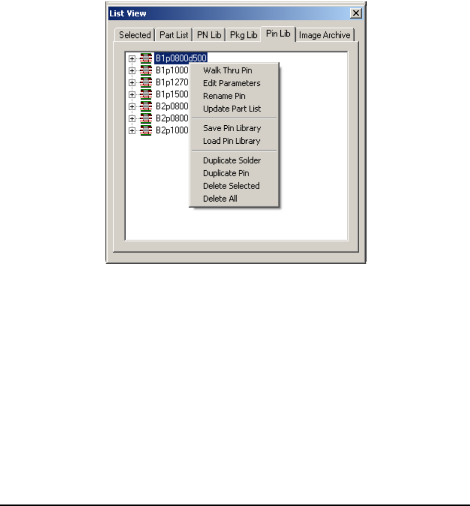
13.6 Pin Library
A pin is one or a stack of multiple solder inspection boxes on 3D slices. One pin is used to
inspect one solder joint of a BGA ball or a PTH pin. The Pin Library is a library that lists the
different types of pins. A new page is added in the List View to show the Pin Library. From the
pin library you can adjust inspection parameters for the pin.

Advance Inspection Features 14-1
14 - Advance Inspection Features
The YesAX software is designed for ease-of-use; hiding the underlying computation
complexities. However, to get the optimal performance for inspecting complex boards with small
components, a working knowledge of the underlying theory is helpful.
14.1 Mathematics of Fiducial Alignment
By default the YesAX software uses two alignment marks to correct for placement differences
between boards. Alignment marks have fixed XY locations. The software uses the fixed XY
locations as a reference to determine what compensation is needed for a particular board under
inspection. The software compensation works best if the alignment marks (fiducials) are located
on the bottom left and the bottom right corner of the board. It is recommended that the user
select the left alignment mark close to the bottom left corner of the board and the right alignment
mark close to the bottom right corner of the board whenever possible.
There are two kinds of positional compensations; one is translational and the other is rotational.
The software uses the left alignment mark to calculate translational compensation. For example,
the left mark has a defined position of (10, 10), and the software finds it to be at (12, 11). This
means in order to compensate the coordinates system needs to shift 2 units to the right in the X
axis and 1 unit up in the Y axis.
After the software compensates translationally, it proceeds to find the right alignment mark and
calculates the rotational compensation using software theta. Software theta is a technique that
mathematically rotates the user coordinate system to compensate for the mis-alignment of the
PCB. For example, there is a 2 degree offset in theta for the PCB. The user wants to go to (1000,
1000) on the PCB to inspect a component. The software calculates the corresponding camera
coordinates using the following algorithm:
X' = X Cos (A) + Y Sin(A)
Y'=-X Sin (A) + Y Cos(A)
In this case
X' = 1000*Cos(2) + 1000 * Sin(2)
Y'=-1000*Sin(2) + 1000 * Cos(2)
X'=1034.29
Y'=964.49
The software then commands the camera to go to (1034.29, 964.49). This is the same place at
(1000, 1000) on the PCB. The process is completely transparent to the user. The reverse
calculation is performed when displaying coordinates. The Status bar will show (1000, 1000).
The YesAX software uses a multi-layer scheme to handle coordinates. The top layer is the user
coordinates (the board or PCB coordinates). This is how the positions of parts on the board are
defined. This is the only coordinate the user will deal with directly. The bottom layer is the
physical coordinate where positions are defined by motor steps and encoder counts. The middle
layers include scaling, software theta, linear error compensation and error mapping. The layering
scheme allows the YesAX to have transferable Inspection Recipes without requiring the
machines to be built identically.