YesAX V3.1.2 - Software User Manual - 第189页
A dvance Inspection Features 14 -3 During system calibration all the video parameters are adjust ed and their values verified against the specification. One critical parameter is the Pixel Size. An accurate Pixel Size pa…
14-2 Advance Inspection Features
In general the 2 fiducials alignment works well, assuming the locations of the left and right
fiducials do not change relative to the board’s origin. This assumption holds true in most cases,
except when the dimensions of the boards change due to temperature or other factors. For
example, on an 8” by 10” PCB, if a higher temperature makes the board expand by 1/1000 then
the right fiducial would be off by 10 mil. In this case using the 2 fiducials alignment method
some parts on the board would be off by 10 mils. For high precision inspection the software also
provides a 3 fiducial alignment method. In addition to providing translational and rotational
compensation, the three fiducials alignment method compensates for expansion and contraction
of the PCB.
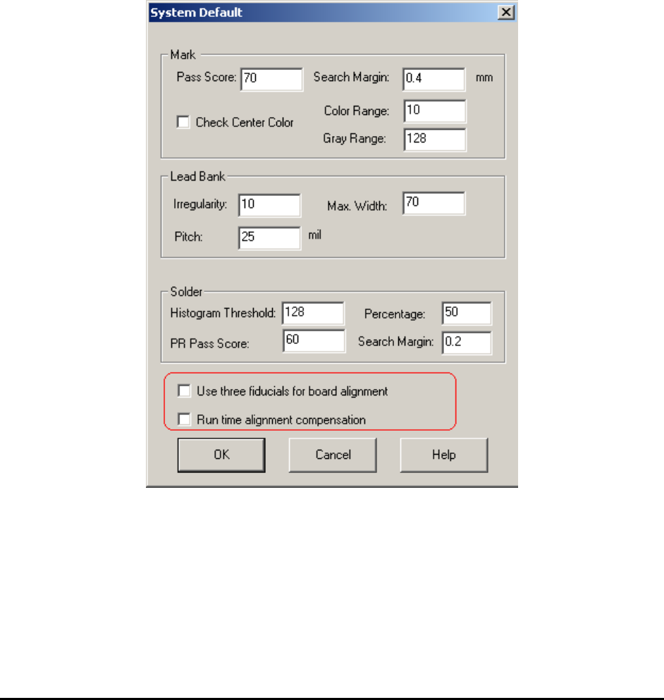
The 2 fiducial alignment technique is the default for board alignment. To use the 3 fiducial
alignment technique, enable it in the System Default dialog. To launch the dialog, select
System>Default Parameters from the main menu.
If you re-define the alignment marks after the feature is enabled, the software will prompt to
train 3 alignment marks.
14.2 Understanding the Video Parameter
Fiducial alignment only ensures that the camera moves to the correct location, which means the
position of the cross hair is where it is supposed to be, as defined in the program. However,
inspections take place in the entire field of view not just where the cross hair is at. The video
parameters ensure all the pixels in the field of view are at their correct locations.
Advance Inspection Features 14-3
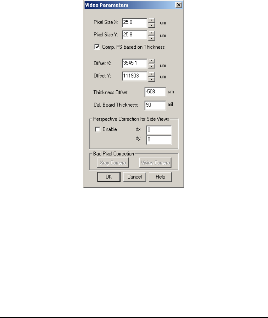
During system calibration all the video parameters are adjusted and their values verified against
the specification. One critical parameter is the Pixel Size. An accurate Pixel Size parameter
allows the software to determine the accurate position of each and every pixel in the field of
view. Because of the cumulative effect, Pixel Size Parameter adjustments are the most critical for
pixels located at the perimeter of the field of view. One way to verify the Pixel Size Parameter
accuracy is to view the overlaid inspection boxes. If an inspection box lines up well with a part
in the middle of the screen but appears off when the part is moved to the edge of the field of
view, it is an indication that the Pixel Size Parameter is inaccurate.
Sometimes the image sensor of an X-ray/Vision camera may have bad pixels which may affect
image quality. The Bad Pixel Correction function is designed to correct this problem. This
function is especially important for X3 AXI systems.
Normally all settings have already been saved during factory calibration and there is no need to
re-adjust those settings.
14-4 Advance Inspection Features
14.3 Part Walk Through Process
Walk Through is the process of stepping through a list of parts one by one. The process is similar
to the Defect Review process. The Walk Through parts process can be started from a number of
places within the List View window based on different part selection criteria. You can walk
through all the locations of the particular part number; you can walk through all the parts with a
particular package, etc.
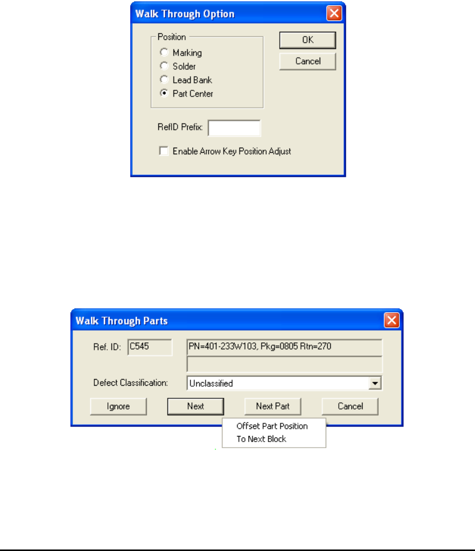
To launch a Walk Through dialog, right click on one of the List View pages and select Walk
Through. The Walk Through dialog below selects the walk through options:
The Position group defines where the Walk Through process will begin.
The RefID Prefix field allows you to select a sub-set of the part in the list to walk through. For
example, if the RefID Prefix is “R”; only the parts with a reference ID starting with “R” will be
visited.
The Enable Arrow Key Position Adjust checkbox allows arrow keys on the keyboard to adjust
a part’s position during the walk through.
The Walk Through Parts dialog is similar to the Review dialog.
The local pop-up menu on the Walk Through dialog has two selections: Offset Part Position
and To Next Block.