YesAX V3.1.2 - Software User Manual - 第226页
在线预览 YesAX V3.1.2 - Software User Manual PDF 文档。

SmartStart 17-3
From this dialog users setup the parameters for SmartStart. In the Selecting Method group, select
one of the following four methods to select recipe:
Hand Held Barcode Read - does NOT require any part in the system part list.
Camera Barcode Read - must have at least one part in the System Part list setup to read
barcode.
Board’s Appearance - train one part per recipe in the set of recipes to be loaded
automatically. Each part should have trained a marking that uniquely identifies that
particular board assembly.
Bottom Barcode Reader - does NOT require any part in the system part list.
Text File Input – does NOT require any part in the system part list.
Cycle Recipes – does NOT require any part in the system part list.
You define the link between the “Cue” and the recipes being loaded. For the methods that
involve barcode, part or all of the barcode is a cue. For the Board Appearance method, the
Reference ID of the corresponding part is the cue. If only a portion of the barcode is used as cue
(e.g. from digit 2 to digit 6), then specify that accordingly.
Inspection recipes on YesAX are for top side only. Specify the Top side to load in the Side group
of the dialog. The Cue Parts Reference Corner group sets the reference corner for all the
reference parts in the system part list. It is only important if the boards in the selection set are of
different sizes.
The Use SmartStart to start all recipe inspections option forces the software to use SmartStart
to start all inspections. When it is checked the Run Recipe button in the toolbar will use
SmartStart instead of the Load Board dialog.
With the help of a custom DataLogExt.DLL the Enable WIP Tracking Integration option
allows the YesAX software to integrate with any WIP (Work in Process) tracking system via
TCP/IP or other interfaces. The message formats are defined in DataLogExt.DLL. You
customize the DataLogExt.DLL for your internal needs.
All the setup parameters for SmartStart, together with the corresponding system part list, can be
saved into disk files for later retrieval. This allows multiple groups of recipes to be SmartStarted.
The SmartStart setups are saved in files with extension .sss. The .sss files can only be located in
the INI folder of the YesAX software. Select the Save SmartStart Setup.. button to save the
SmartStart setup.
Defect and Board Documentation 18-1
18 - Defect and Board Documentation
18.1 Screen Image
In addition to use inline inspection for defect detection, the AXI machine is also a wonderful tool
for manual inspection. Use the AXI machine to capture pictures of defects and sample boards
and then create rework documents. Several software features are designed for such applications.
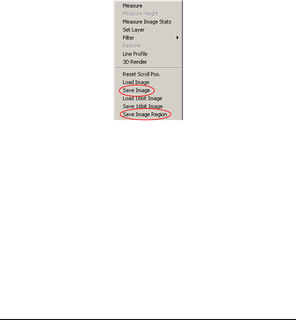
Save Image and Save Image Region, from the Video View menu, saves the image or image
region to a file in a user selectable format (bitmap, tiff, JPEG, etc.) to a user-defined file
path/name.
For X3 AXI system, since the X-Ray detector has 16-bit capability it is also possible to save and
load 16bit images for your applications.
One of the very powerful but often forgotten features in Windows XP is the Print-Screen
function. This is a handy tool for documentation. To use the feature just press the PrtScn key
combination (Shift- PrtScn or Fn- PrtScn) on the key board, launch the Microsoft Paint
program and select Edit, Paste. You can use MS Paint do all sorts of editing for the screen
image before saving it to file. In fact, most of the software images in this manual are created by
using this method.
18.2 Part Image
For PCBs used in products that require total traceability (medical products, safety devices),
YesAX software can capture images of specified parts. The part images are stored in the
PartImage sub-folder under the Recipe folder. It is saved in JPEG format. Part Images are
stitched from inspection images. If the part is inspected in multiple views, there will be multiple
images for that part. The part image file name is composed of the board’s serial board, the part’s
reference ID and the view that captured the image: BoardSN_RefID_View.jpg.
To specify a part for part image save, check the Save This Part Image checkbox in its Edit Part
Parameters dialog.