YesAX V3.1.2 - Software User Manual - 第62页
6-4 Recipe Creat ion Step by Step for 2D Rec ipes
Recipe Creation Step by Step for 2D Recipes 6-3
Here is a sample fragment of the Part List section.
[PartList]
RefID. P/N XPos YPos Rtn Pkg Extensions
FiduLeft ---- 12.097 10.471 0.00 ----
FiduRight ---- 211.93 5.17 0.00 ----
R63 ---- 157.41 113.29 0.00 ----
R132 ---- 72.19 51.21 270.00 ----
R102 302-111W000 100.94 76.60 270.00 1206 RES,SMT,1/8W,1%,0.00
R125 302-111W000 214.08 67.67 270.00 1206 RES,SMT,1/8W,1%,0.00
R73 302-111W001 156.89 103.89 0.00 1206 RES,SMT,1/8W,1%,10.00
R74 302-111W001 170.88 103.89 0.00 1206 RES,SMT,1/8W,1%,10.00
R93 302-111W001 164.51 91.82 270.00 1206 RES,SMT,1/8W,1%,10.00
R100 302-111W001 156.24 85.48 270.00 1206 RES,SMT,1/8W,1%,10.00
R887 302-111W043 204.94 96.19 270.00 1206 RES,SMT,1/8W,1%,27.00
R888 302-111W043 162.03 80.65 0.00 1206 RES,SMT,1/8W,1%,27.00
R891 302-111W043 158.58 65.15 0.00 1206 RES,SMT,1/8W,1%,27.00
R892 302-111W043 158.58 68.45 0.00 1206 RES,SMT,1/8W,1%,27.00
R72 302-111W069 144.11 102.00 270.00 1206 RES,SMT,1/8W,1%,51.10
[PartListEnd]
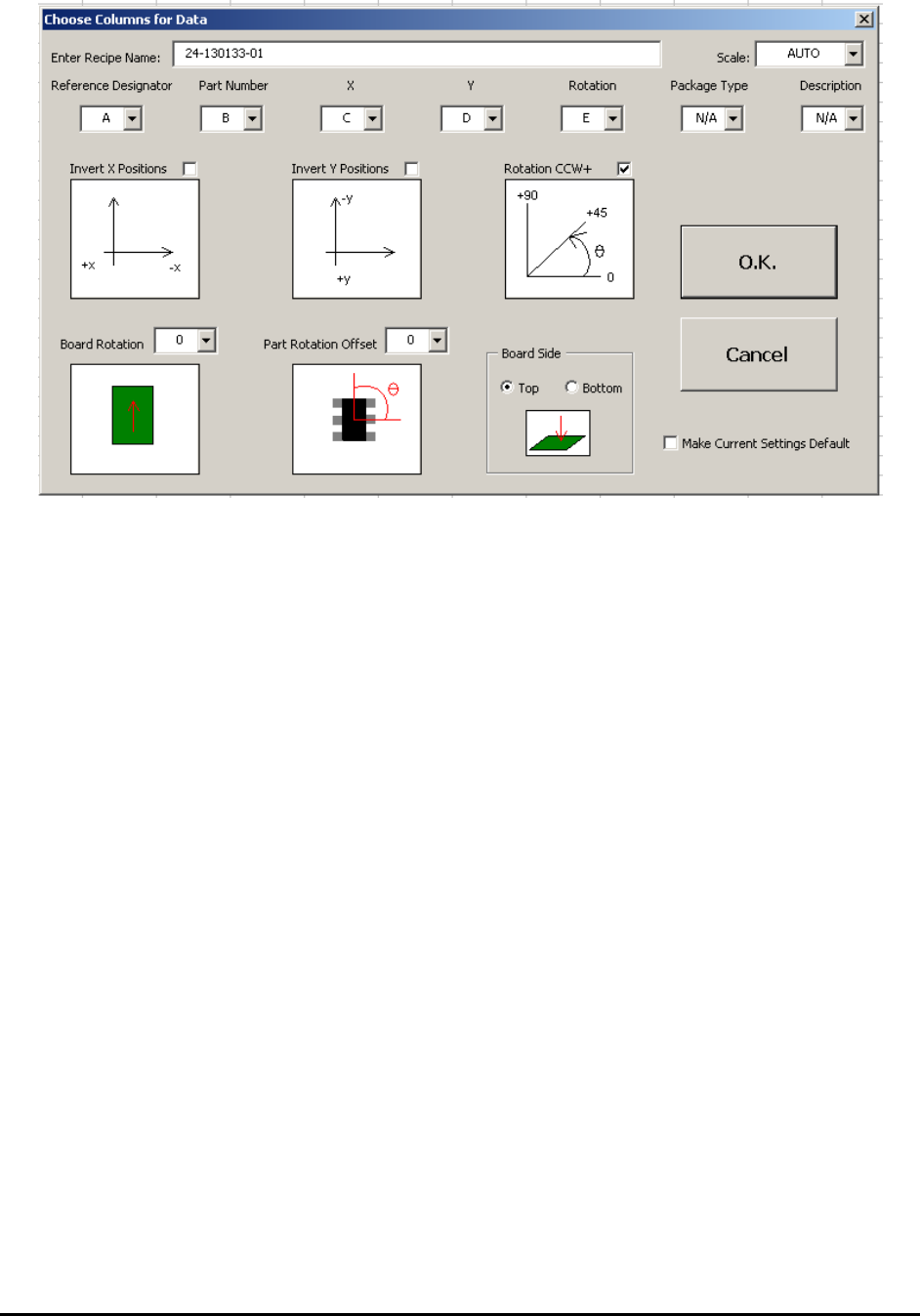
The Nordson YESTECH CAD Utility gathers header information from the graphical user
interface and collects CAD data in any column format to generate the YCD file. The following
are some of the screen shots of the CAD utility.
6-4 Recipe Creation Step by Step for 2D Recipes
Recipe Creation Step by Step for 2D Recipes 6-5
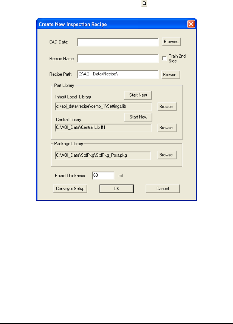
6.2 Step2: Define New Board Parameters
After the YCD file is created, press the New Board button to start creating a new inspection
recipe. The Create New Inspection Recipe dialog displays.
Press the Browse button on the right of the CAD data box to load the corresponding CAD data
file (.YCD). With the exception of the Recipe Path box, the information from the Header section
of the CAD data automatically populates the other text boxes in the dialog.
Press Ok on the Create New Inspection Recipe dialog to start the interactive process of defining
board size, defining alignment marks, and capturing the board image. Depending on the
information provided in the CAD data some of the steps may be skipped. Here is a flow chart of
the process: