00191025-01.pdf - 第101页
SIPLACE 80S/F/G User’s Manual 5 Placement Edition 12/96 from S oftware Version SR.009.xx 5.6 Error Menu s 5 - 25 5.6 Error Men us 5.6.1 General The erro r menus app ear automati cally on th e screen af ter a fatal er ror…

5 Placement SIPLACE 80S/F/G User’s Manual
5.5 PCB Handling Edition 12/96 from Software Version SR.009.xx
5 - 24

SIPLACE 80S/F/G User’s Manual 5 Placement
Edition 12/96 from Software Version SR.009.xx 5.6 Error Menus
5 - 25
5.6 Error Menus
5.6.1 General
The error menus appear automatically on the screen after a fatal error. A fatal error means that the machine
cannot continue with placement without the intervention of the operator. When the error menus appears, you
are requested to press the start key in order to move the portal into the waiting position.
The menus "Track error 1" and "Track error 2" refer to the components table affected in each case. Since both
menus are identical, only the menu "Track error 1" will be described in this manual.
The menus "Machine error 1" and "Machine error 2" refer to the portal affected in each case. Since both
menus are also identical, here too only the menu "Machine error 1" will be described.
NOTE
As a standard procedure, only those functions are shown in the error menus which the operator can perform.
Only when the line engineer password has been entered is the full range of functions of the error menus
available.
All error menus can only be quit via the functions "Continue placement" or "Abort placement".
Following this error message you must select "Abort placement" once again if an operating error is to be
prevented.
WARNING
∆
!
∆
!
The functions, which are only accessible after the line engineer password has been entered, may only be
implemented by appropriately qualified and trained personnel, since improper handling of them may result in
injuries and/or damage to the machine.
NOTE
In the menus Track error, Machine error and Nozzle change the protective cover is unlocked and the x and y
axes isolated. In these menus, the axes can only be moved when the protective cover has been closed.
If head functions are selected, the key-operated switch will have to be turned with the cover open in order to
allow head functions to be used (for example, cycle star).
If the key-operated switch is activated when the protective cover is closed, the axes will be able to travel only
at the lower speed.
5 Placement SIPLACE 80S/F/G User’s Manual
5.6 Error Menus Edition 12/96 from Software Version SR.009.xx
5 - 26
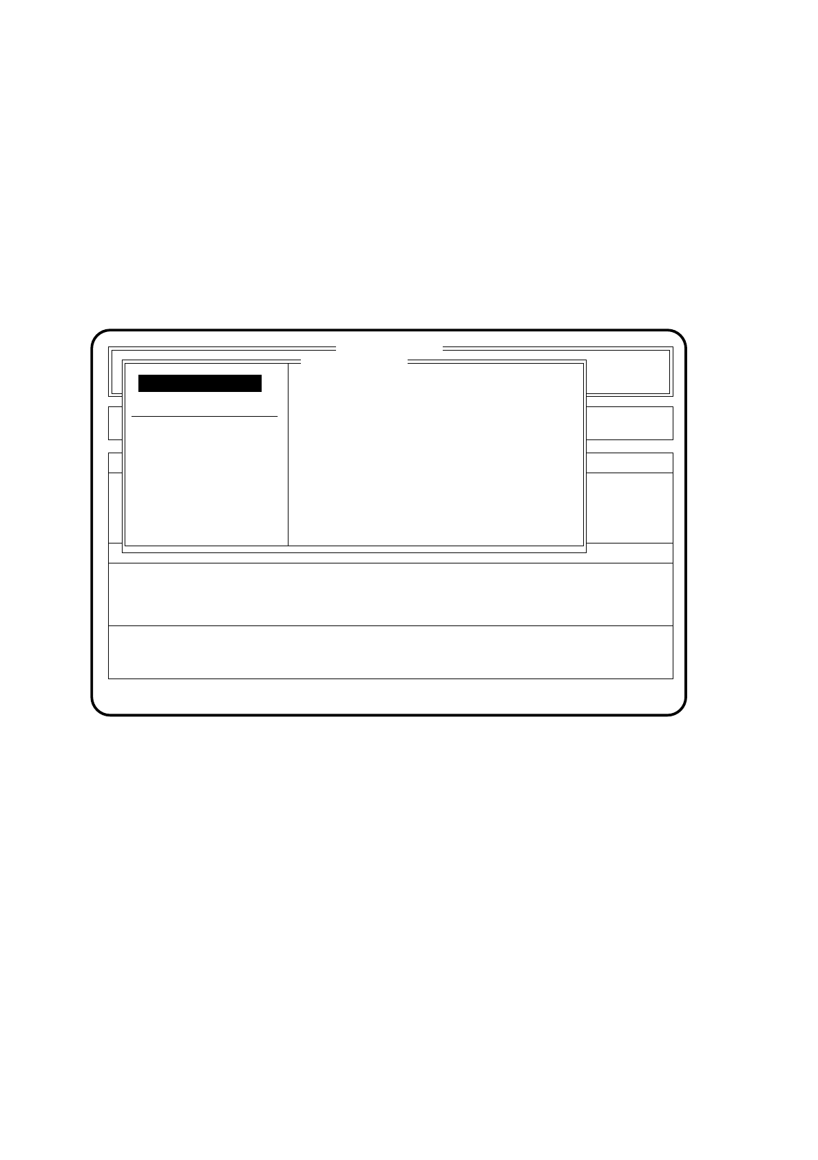
5.6.2 Transport Error Menu
The transport error menu appears on the screen when errors occur while the printed circuit board is being
transported. Possible errors include for example: the ultrasound sensors do not respond correctly, or the
printed circuit board is not stopped or clamped.
5.6.2.1 Range of Functions for the Operator
Fig. 5.6.1
PCB to output conveyor
When the function "PCB to output conveyor" is selected via the cursor keys and the
Return key
, a printed
circuit board on the center conveyor is conveyed onto the output conveyor and left there for removal by
hand. Components already picked up remain at the placement head.
PCB to center conveyor
When the function "PCB to center conveyor" is selected via the cursor keys and the
Return key
, a printed
circuit board on the input conveyor is transported onto the center conveyor, stopped and clamped.
Display errors
To obtain a display of all errors which have occurred, use the
cursor keys
to select the menu point "Display
errors". Then press the
Return key
. On the screen the menu "Display errors" described in Section 5.7 (Dis-
play functions) will appear.
SI 80 V 9.x
Nutzen:
Rüstung :
Error
State
Action
:
:
:
Transport error
Abort placement
Display errors
PCB to center conveyor
PCB to output conveyor
Error treatment - transport errors
Continue placement
Continue placement