00191025-01.pdf - 第106页
5 Placement SIPLACE 80S /F/G User’s Manual 5.6 Error Menus Edition 12/96 from Software Version S R.009.xx 5 - 30 5.6.3.1 Range of Functions for the Operator Display er rors To obta in a d isplay of all errors wh ich ha v…

SIPLACE 80S/F/G User’s Manual 5 Placement
Edition 12/96 from Software Version SR.009.xx 5.6 Error Menus
5 - 29
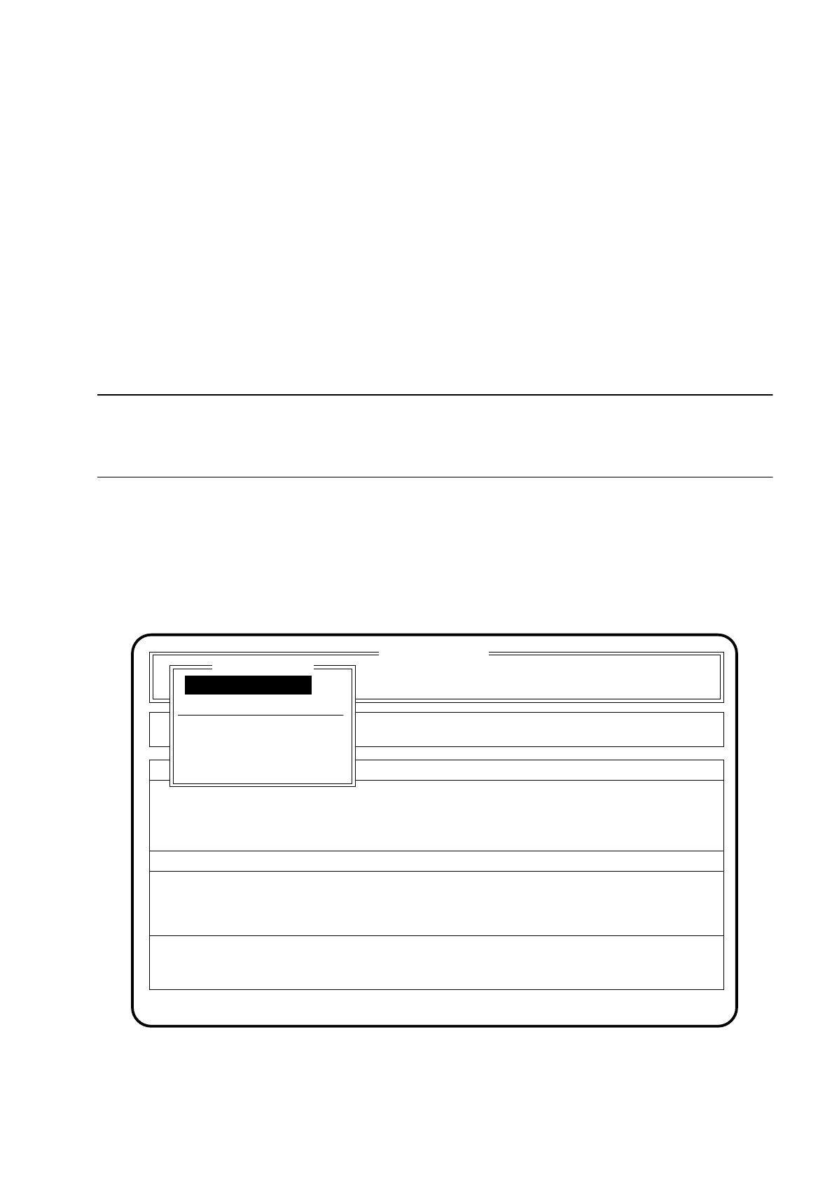
5.6.3 Fiducial Error Menu
If a fiducial is not found or not recognized during position recognition, the fiducial error menu appears auto-
matically on the screen.
Fig. 5.6.2
SI 80 V 9.x
Cluster: TEST
Neuer Nutzen
Display errors
Confirm errors
Machine options
Error
State
Action
:
:
:
Error treatment - fiducial error
Abort placement
PCB to output conveyor
PCB to center conveyor
Display errors
Continue placement
Fiducial error
Continue placement

5 Placement SIPLACE 80S/F/G User’s Manual
5.6 Error Menus Edition 12/96 from Software Version SR.009.xx
5 - 30
5.6.3.1 Range of Functions for the Operator
Display errors
To obtain a display of all errors which have occurred use the
cursor keys
to select the menu point "Display
errors". Then press the
Return key
. On the screen the menu "Display errors" described in Section 5.7
(Display functions) will appear.
Abort placement
Use the
cursor keys
to select the menu item "Abort placement" in order to quit the error menu without
placement continuing, and press the
Return key
. The board on the conveyor is transported onto the output
conveyor. Components at the placement head are ejected. The portals are moved into the waiting position.
Continue placement
Use the
cursor keys
to select the menu item "Continue placement" in order for placement to continue and
press the
Return key
. The machine checks whether there is a board on the center conveyor (placement
area) and continues placement. If there is no board in the placement area, a request is issued under menu
item "Action" of the basic menu.
PCB to output conveyor
When the function "PCB to output conveyor" is selected via the cursor keys and the
Return key
, a printed
circuit board on the center conveyor is conveyed onto the output conveyor and left for removal by hand.
Components which have already been picked up remain at the placement head.
PCB to center conveyor
When the function "PCB to center conveyor" is selected via the cursor keys and the
Return key
, a printed
circuit board on the input conveyor is transported onto the center conveyor, stopped and clamped.
Replacing the printed circuit board without losing the components:
●
Using the
cursor keys
position the cursor bar over the menu item "PCB to output conveyor".
Then press the
Return key
.
The printed circuit board is transferred to the output conveyor and can be removed there. The components
that have been picked up remain at the head.
●
Load a printed circuit board onto the input conveyor. Using the
cursor keys
position the cursor bar over the
menu item "PCB to center conveyor". Then press the
Return key
.
The printed circuit board is transferred to the center conveyor and clamped.
●
Using the
cursor keys
position the cursor bar over the menu item "Continue placement".
Then press the
Return key
.
SIPLACE 80S/F/G User’s Manual 5 Placement
Edition 12/96 from Software Version SR.009.xx 5.6 Error Menus
5 - 31
5.6.3.2 Range of Functions for the Line Engineer
After entering the line engineer password the following additional functions are displayed in the transport error
menu:
Cycle mode
Using the
cursor keys
position the cursor bar over the menu item "Cycle mode". Then press the
Return
key
. For each step of the placement sequence you will now need to press the start button.
5.6.4 Track Error Menus 1 and 2
NOTE
After the start key has been pressed the placement head moves out of the feeder area to allow work to be
carried out on the feeders.
The track error menu is shown on the screen when no further mountable component can be found. This
means that a component which cannot be found in the component feeders is passed over. Placement is con-
tinued up until the point where only the components which are still missing need to be placed on the board.
After the track error menu has been processed, the remaining components are placed on the printed circuit
board (Repair run).
Fig. 5.6.3
SI 80 V 9.x
Cluster: TEST
Rüstung :
Display errors
Confirm errors
Machine options
Error
State
Action
:
:
:
Track error 1/2
Abort placement
Display errors
Refill
Error treatment - pick-up error
Continue placement
Continue placement