00191025-01.pdf - 第15页
SIPLACE 80S/F/G User’s Manual 0 Introduction Edition 07/97 from S oftware Version SR.010.xx 0.2 Technical Data 0 - 11 0.2.1.4 Boards, Components, Tapes (80S) Diodes Forward v oltage Accurac y I-Meas. Comme nt 0.1 to 5 V …
0 Introduction SIPLACE 80S/F/G User’s Manual
0.2 Technical Data Edition 07/97 from Software Version SR.010.xx
0 - 10
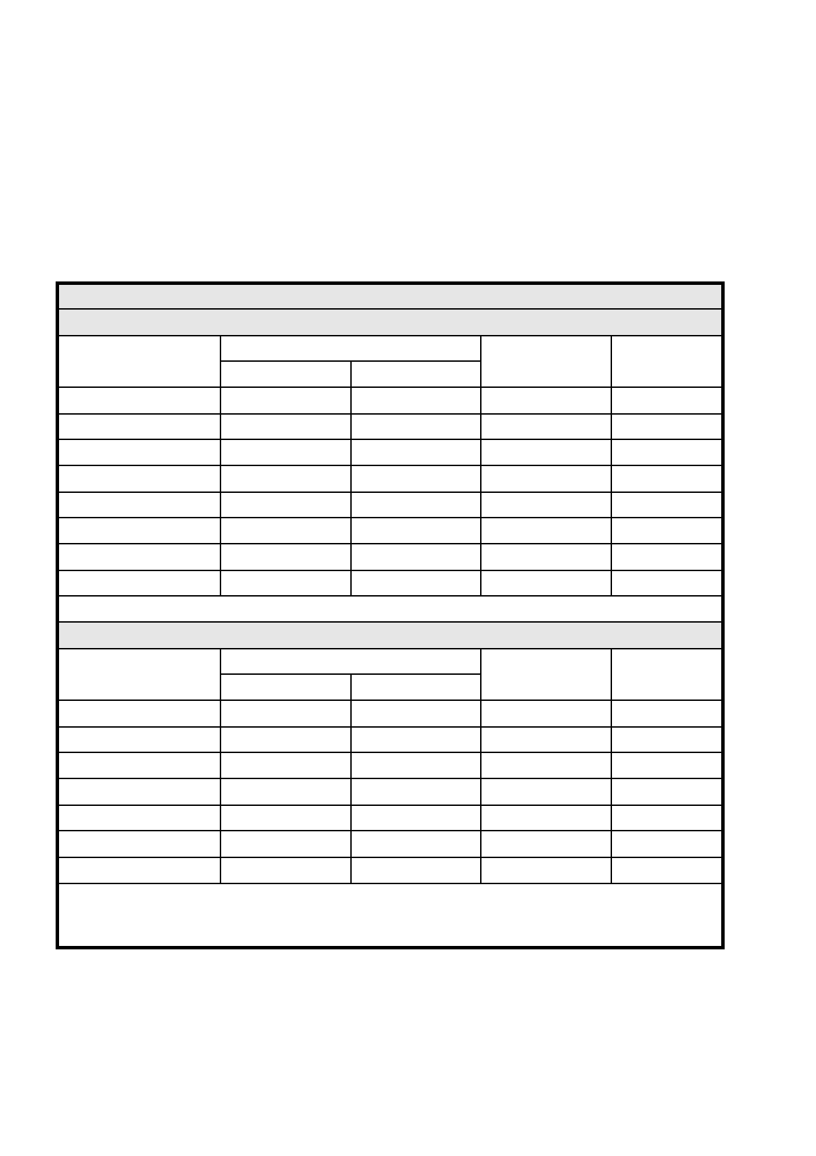
0.2.1.3 CRDL Tester 80S
Note concerning the tables
The figures for accuracy are composed of two values.
-
The measurement tolerance in % of reading (rdg)
-
A basic error (abs.) which is inherent in every range of measurement
E.g. measured value 200 pF ± 3 % Tol.: (±) 6 pF + (±) 2 pF (rdg) = ± 8 pF measurement tolerance
CRDL tester
C test
Range of measurement
Accuracy
Measurement
voltage at 1.6 kHz
Comment
Tol. [%] (rdg) abs.
from 10 to 100 pF ± 3 % ± 1 pF 5 V min. 10 pF
from 100 pF to 1 nF ± 3 % ± 2 pF 5 V
from 1 nF to 10 nF ± 3 % ± 20 pF 0.5 V
from 10 nF to 100 nF ± 3 % ± 100 pF 0.5 V
from 100 nF to 1
µ
F ± 4 % ± 1 nF 0.5 V
from 1
µ
F to 10
µ
F ± 4 % ± 20 nF 0.5 V
from 10
µ
F to 100
µ
F ± 5 % ± 100 nF 0.5 V
from 100
µ
F to 220
µ
F ± 5 % ± 200 nF 0.5 V max 220 µF
Polarity measurement of the tantalum capacitors has not yet been approved.
R test
Range of measurement
Accuracy
Measurement
voltage at 1.6 kHz
Comment
Tol. [%] (rdg) abs.
10
Ω
to 100
Ω
± 3 % ± 1
Ω
0.5 V min. 10
Ω
100
Ω
to 1 k
Ω
± 3 % ± 2
Ω
0.5 V
1 k
Ω
to 10 k
Ω
± 3 % ± 50
Ω
0.5 V
10 k
Ω
to 100 k
Ω
± 3 % ± 200
Ω
0.5 V
100 k
Ω
to 1 M
Ω
± 3 % ± 500
Ω
5 V
1 M
Ω
to 10 M
Ω
± 5 % ± 20 k
Ω
5 V
10 M
Ω
to 22 M
Ω
± 10 % ± 100 k
Ω
5 V max. 22 M
Ω
In the range of measurement below 100
Ω
it will be necessary in the tolerance stated to take into account the possible
ground leakage resistance through oxidation layers on the component or deposits
on the measuring jaws. (Up to 6
Ω
has been measured during trials)
SIPLACE 80S/F/G User’s Manual 0 Introduction
Edition 07/97 from Software Version SR.010.xx 0.2 Technical Data
0 - 11
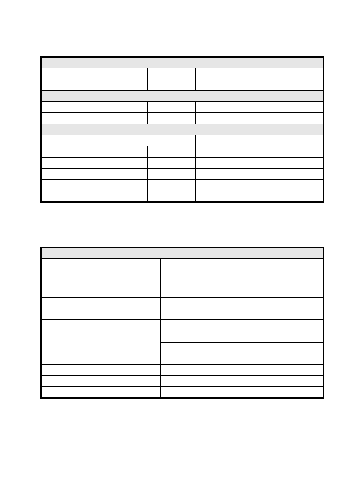
0.2.1.4 Boards, Components, Tapes (80S)
Diodes
Forward voltage Accuracy I-Meas. Comment
0.1 to 5 V ± 10 % 5 mA ± 10 % Reverse voltage must be greater than 23 V
Z diodes
Zener voltage Accuracy I-Meas. Comment
2 V to 22 V ± 10 % 5 mA ± 10 % Forward voltage must be between 0.3 and 0.9 V
L measurement
Range of meas.
Accuracy
Measurement voltage at 1.6 kHz
Tol. [%] (rdg) abs.
200 µH to 1 mH ± 5 % ± 5 µH 0.5 V
1 mH to 10 mH ± 5 % ± 100 µH 0.5 V
10 mH to 100 mH ± 5 % ± 200 µH 0.5 V
100 mH to 820 mH ± 5 % ± 500 µH 0.5 V
Boards, components, tapes
Boards (PCB) transport system In-line transport with width adjustment
PCB format
50 mm x 50 mm to 460 mm x 460 mm with PCB buffer
50 mm x 50 mm to 508 mm x 460 mm
without PCB buffer (upon request)
Component-free guide edge of the board 3 mm
Min. PCB thickness 0.5 mm
Max. PCB thickness 4.5 mm
Max. PCB warpage
Upwards : 4.5 mm less PCB thickness
Downwards: 0.5 mm plus PCB thickness
PCB change time 2.5 sec.
Max. component height 6 mm
Max. number of 8 mm tapes 80
Tape reel diameter Max. 15" in the reel container
0 Introduction SIPLACE 80S/F/G User’s Manual
0.2 Technical Data Edition 07/97 from Software Version SR.010.xx
0 - 12
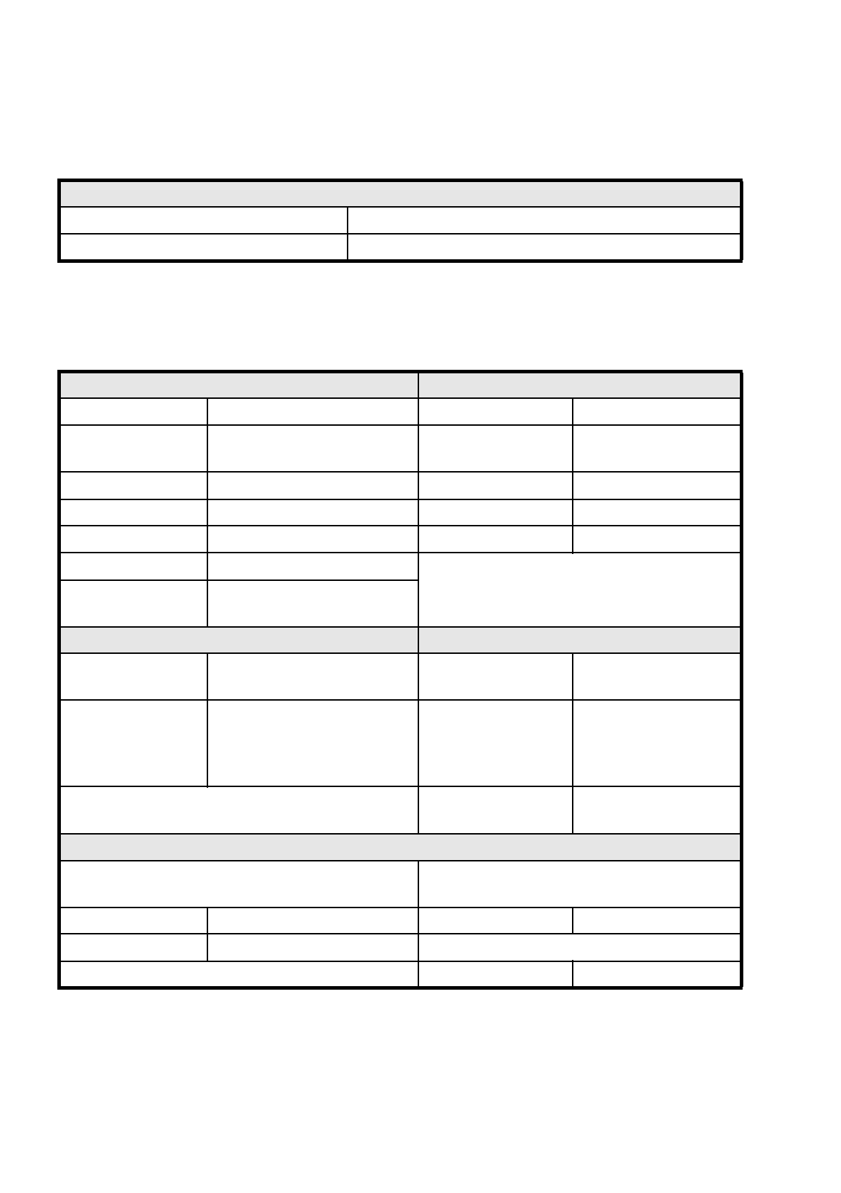
0.2.1.5 Interfaces 80S
0.2.1.6 Connection and Installation Data 80S
Interfaces 80S
Electrical Siemens handshaking interfaces in the placement machines
Mechanical Conveying height: 830 mm ± 15 mm
Connection and Installation requirements Machine dimensions
System voltage 230/400V ± 10 % (50/60 Hz) Weight base module 1500 kg
System voltage
opt. e.g. for USA
110/208 V ± 10 % (50/60 Hz) Weight fully-equipped 2000 kg
Total connected load 5 kVA Length 1587 mm
Total output 5 kW Width 2425 mm
Fuse protection 3 x 16 A Height with warning light 1836 mm
Compressed air supply At least 6 bar 600 NL/min.
Machine footprint
Permissible surface load
> 1 t/m²
Permissible environmental influences Machine control
Room temperature Between 15°C and 35°C Control computer
PC 386,
RMOS operating system
Air humidity
30 to 75 % (on average not higher
than 45 %, so that under no cir-
cumstances will there be conden-
sation in or on the machine
Machine control
SIMICRO
Input / output control
Axis controller
Siemens axis controller
boards (digital)
Compressed air specification
Max. particle size by density, based on ISO/DIS 8573-1
(Class 1)
Maximum oil content
Class 1
Particle size 0.1 µm Particle density 0.01 mg/m³
Particle density 0.1 mg/m³ Pressure dewpoint Class 4
Dewpoint + 3°C