00191025-01.pdf - 第203页
SIPLACE 80S/F/G User’s Manual 7 Vision Systems Edition 07/97 from S oftware Version SR.010.xx 7.1 Survey of the Vision S ystems of the SIPLAC E 80 S/F/G Machines Line engi neer 7 - 11 Fig. 7.1.9 Evaluation unit for the S…
7 Vision Systems SIPLACE 80S/F/G User’s Manual
7.1 Survey of the Vision Systems of the SIPLACE 80 S/F/G Machines Edition 07/97 from Software Version SR.010.xx
7 - 10 Line engineer
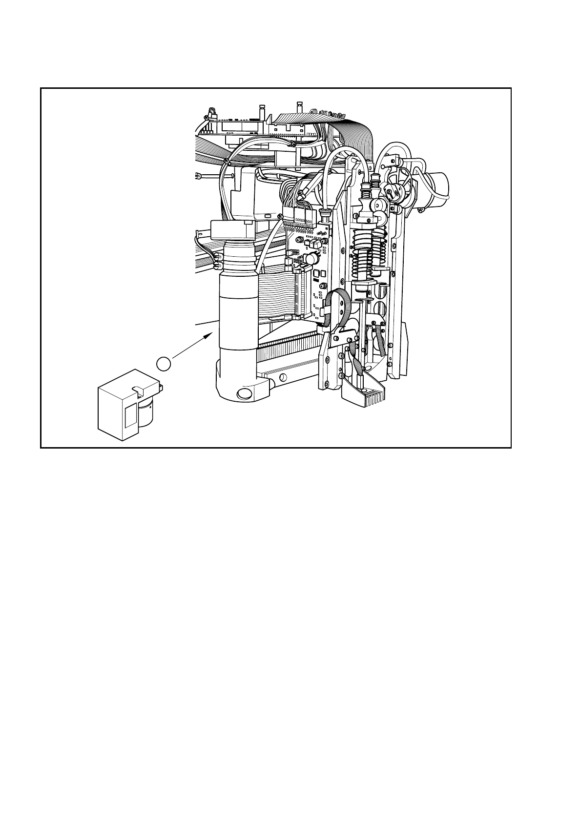
Fig. 7.1.8 Location of the PCB camera in the SIPLACE G adhesive application station
Key to Fig. 7.1.8:
➀
PCB camera on the underside of the gantry
Fig. 7.1.8 indicates the position of the PCB camera in the SIPLACE G machine.
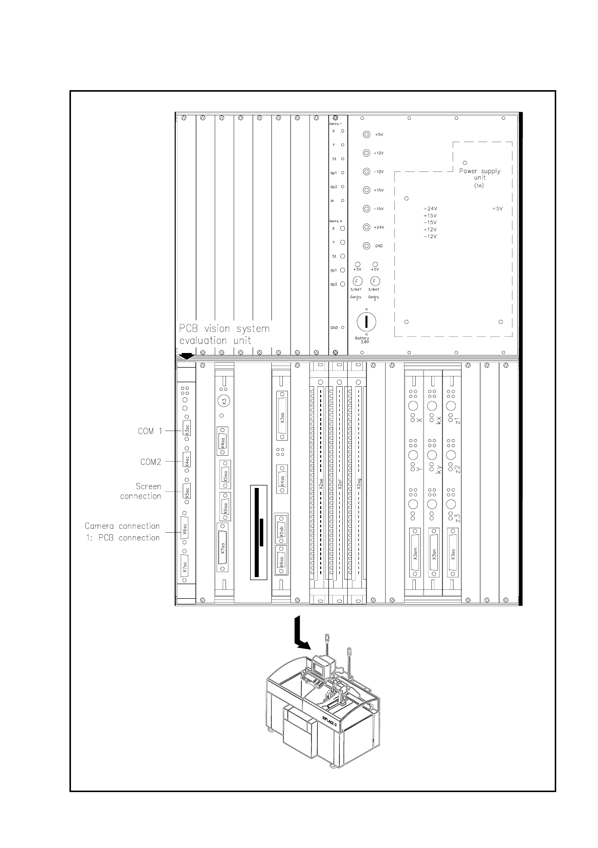
The vision evaluation unit - accommodated in the control unit of the machine (see Fig. 7.1.9) - processes the
signals of the PCB camera system. From the setpoint deviations correction values are determined, which are
in turn used in the recalculation of the adhesive spot positions.
1
SIPLACE 80S/F/G User’s Manual 7 Vision Systems
Edition 07/97 from Software Version SR.010.xx 7.1 Survey of the Vision Systems of the SIPLACE 80 S/F/G Machines
Line engineer 7 - 11
Fig. 7.1.9 Evaluation unit for the SIPLACE G adhesive application system

7 Vision Systems SIPLACE 80S/F/G User’s Manual
7.1 Survey of the Vision Systems of the SIPLACE 80 S/F/G Machines Edition 07/97 from Software Version SR.010.xx
7 - 12 Line engineer