00191025-01.pdf - 第204页
7 Vision Systems SIPLACE 80S /F/G User’s Manual 7.1 Survey of the Vision Systems of the SIPLACE 80 S/F/G Machines Ed ition 07/97 from Software Version SR.010.xx 7 - 12 Line engine er
SIPLACE 80S/F/G User’s Manual 7 Vision Systems
Edition 07/97 from Software Version SR.010.xx 7.1 Survey of the Vision Systems of the SIPLACE 80 S/F/G Machines
Line engineer 7 - 11
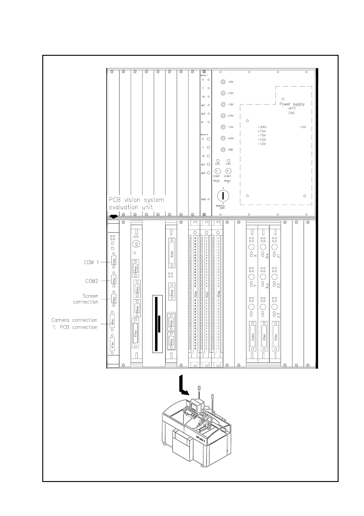
Fig. 7.1.9 Evaluation unit for the SIPLACE G adhesive application system

7 Vision Systems SIPLACE 80S/F/G User’s Manual
7.1 Survey of the Vision Systems of the SIPLACE 80 S/F/G Machines Edition 07/97 from Software Version SR.010.xx
7 - 12 Line engineer

SIPLACE 80S/F/G User’s Manual 7 Vision Systems
Edition 07/97 from Software Version SR.010.xx 7.2 PCB Vision System
Line engineer 7 - 13
7.2 PCB Vision System
The PCB vision system senses the precise position of the board by scanning the fiducials and determines the
offset in x and y directions, the rotation angle relative to the direction of PCB transport and the shear of the
PCB. Even reject fiducials (ink dots) are registered by the PCB vision system and evaluated.
7.2.1 Description of the System
The PCB vision system for PCB position recognition consists of
●
the optical system for PCB position recognition.
Each revolver head is equipped with its own PCB position recognition system (see Fig. 7.1.2).
On auto-
matic glue application machines, the PCB camera system is located beneath the gantry
(see Fig. 7.1.8,
page 7 - 10).
PLEASE NOTE:
PCB position recognition is only carried out with gantry 1.
●
the vision evaluation unit.
For each gantry one evaluation unit for the position recognition of PCBs and components is installed in the
control unit (see Figures 7.1.3, 7.1.6 and 7.1.9). The adhesive application head is only equipped with one
system for PCB position recognition.
A CCD camera (Sony XC77 camera) with integrated imaging and lighting lens constitutes the optical PCB
position recognition system. The field of view of the PCB module equals 5.7 mm x 5.7 mm. Within the dimen-
sions of the visual fields a search area can be freely programmed with respect to position and size. The imag-
ing lens is a special measuring lens which provides the most extensive compensation for measurement errors
due to warping of PCB's. The lighting is only switched on when fiducials are being scanned.
The vision evaluation unit (MVS) is a single-board system in accordance with the VME standard. The hard-
ware consists of:
●
the MVS100 motherboard with vision processor and interface connections
The rear side of the board accommodates the
–
plug connections for the VME bus and
–
the very-high-speed communications unit (HS
3
L)
The front side of the board accommodates the connectors for
–
the screen
–
up to 4 camera inputs
–
two serial interfaces (RS232 or RS422)
Placement System PCB camera MVS evaluation unit
80S (2 gantries) 2 2
80F (1 gantry) 1 1
G (1 gantry) 1 1