00191025-01.pdf - 第207页
SIPLACE 80S/F/G User’s Manual 7 Vision Systems Edition 07/97 from S oftware Version SR.010.xx 7.2 PCB Vision Sys tem Line engi neer 7 - 15 tion of t he fiduci al coordi nates – 1D pa ttern search procedure (1 -dimensio n…

7 Vision Systems SIPLACE 80S/F/G User’s Manual
7.2 PCB Vision System Edition 07/97 from Software Version SR.010.xx
7 - 14 Line engineer
and the display LED's for
–
the CPU
–
the vision processor
–
the camera input
–
the screen display.
The switches for “RESET” and “ABORT” are located below the display LED's
●
the MVS500 camera interface (piggyback board) for up to four CCD cameras.
7.2.2 Technical Data
Camera type: SONY XC77
Number of pixels: camera 768 (H) x 494 (V)
image 640 (H) x 484 (V)
Field of view: 5.7mm x 5.7 mm
Lighting method: incident-light illumination (is activated during measurement)
Image processing: correlation principle, grey-scale system
Processor cycle time: < 200 msec
Screen: RGB monitor (VGA mode) 640 x 484 pixels of the stations
computer
Fiducials: library for up to 255 fiducial definitions
7.2.3 Description of Function
Before placement position, rotation angle and shear of the board are determined on the basis of the positions
of the fiducials by the PCB vision system. Deviations from the setpoint values are then included in the calcula-
tion of the placement positions of the components as corrections.
At least 2 fiducials must be marked on a board so that the system can recognize deviations in the PCB posi-
tion and in the PCB rotation angle. Where 3 fiducials are marked, you will be additionally provided with infor-
mation on compression and deformations of the board and of the board layout.
7.2.4 Functional Sequence
Before a fiducial can be used for PCB recognition, it must first have been “taught”, i.e. the fiducial structure
parameters must be stored in the PCB vision system for the pattern.
●
The fiducial structure is taught using the PCB vision camera fitted to the placement head and the vision
program.
The vision evaluation unit determines the significant fiducial structure parameters using methods of digital
image processing.
●
Measurement takes place in two steps:
–
2D pattern search procedure (2-dimensional procedure) in the rough grid and provisional determina-
SIPLACE 80S/F/G User’s Manual 7 Vision Systems
Edition 07/97 from Software Version SR.010.xx 7.2 PCB Vision System
Line engineer 7 - 15
tion of the fiducial coordinates
–
1D pattern search procedure (1-dimensional procedure) for precise determination of the position of
the fiducials.
With the 2D pattern search procedure the template window is divided into in moxel areas. Moxels (
mo
saic pi
x-
el
s) are pixel fields with, for example, 16 x 16, 8 x 8 pixels etc. The lower the number of pixels, the higher the
resolution and the lower the search speed.
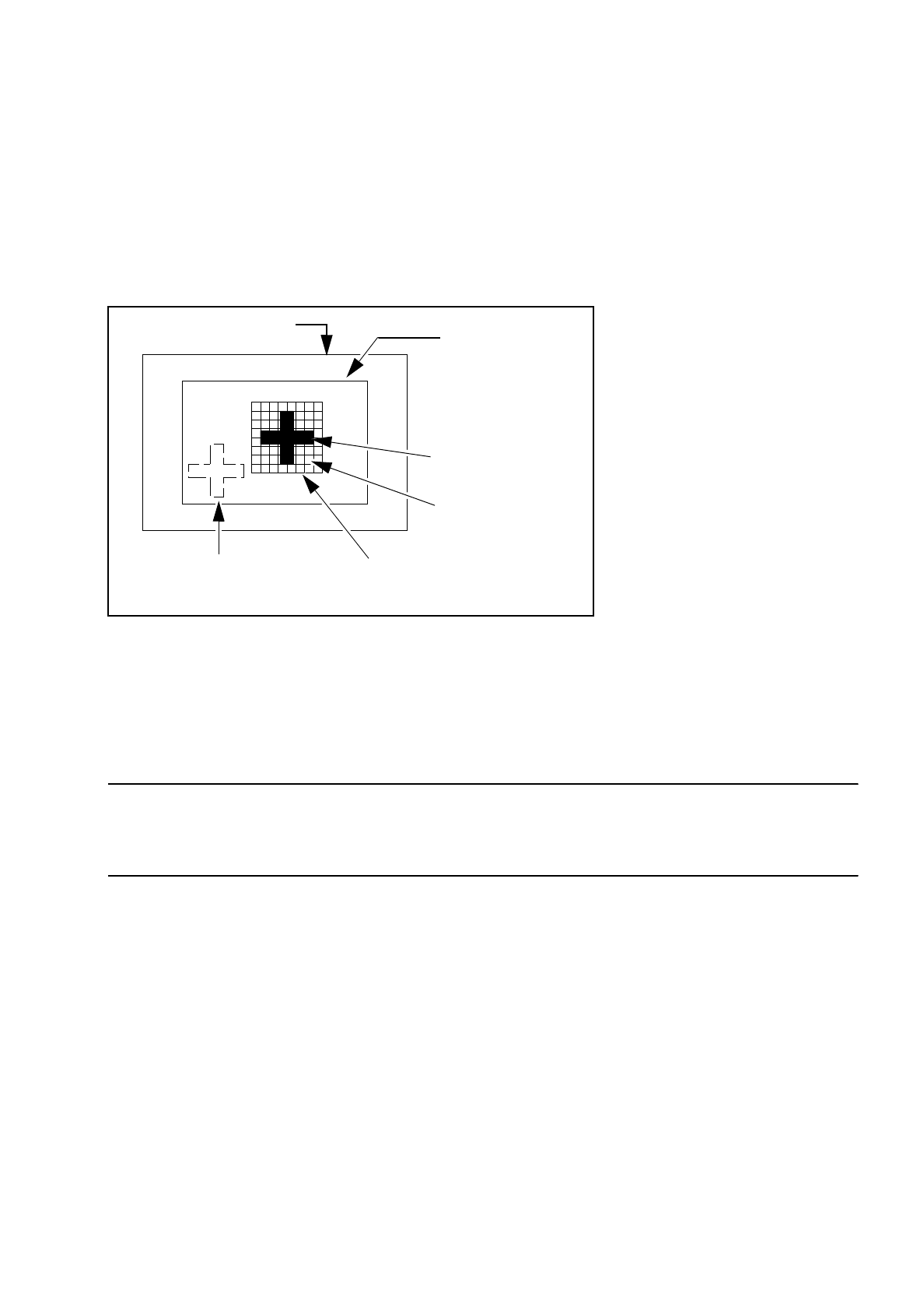
Fig. 7.2.1 Explanation of camera field of view, search area and template window
The template window is moved over the search area in moxel steps. The grey-scale values of each individual
moxel of the reference pattern are calculated. This reduced data structure contains enough information on the
rough structure and position of the reference pattern.
NOTE
The search window should be selected as small as possible in order to achieve a high search speed, but
should still be large enough to ensure clear reidentification of the fiducial.
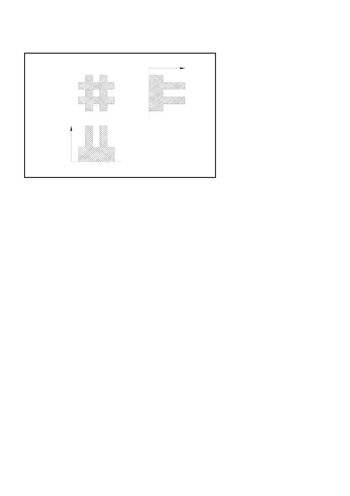
The 1D pattern search procedure is used for the exact determination of the pattern and position of the fiducial.
The fiducial image is analyzed by column and row and the grey-scale values within each individual column
and row added up. The next Figure shows this procedure using a double cross.
Search area for the
camera
≤
field of view
(The fiducial is
searched for within
this area)
Reference pattern
Moxel = pixel field
e.g. 16 x 16 pixels
Field of view of the camera
Fiducial to be found
Template window
(It contains the reference fiducial)
7 Vision Systems SIPLACE 80S/F/G User’s Manual
7.2 PCB Vision System Edition 07/97 from Software Version SR.010.xx
7 - 16 Line engineer
Fig. 7.2.2 Row and column profiles of a double cross
●
The position of the fiducial is precisely determined from the horizontal and vertical profiles. After teaching
is completed the fiducial structure parameters obtained are saved to the line computer.
●
Now the saved definition is tested. The gantry of the PCB camera moves over the board to all 4 corners of
the search area (worst case). In this test the vision system must reidentify the fiducial four times.
●
Finally, the coordinates of each individual fiducial (at least two) are entered manually into the NU-file or
transferred from the CAD file into the NU-file. In this way the coordinates and fiducial structure parameters
for the board which is to be placed are defined in the system as a model.
●
During the placement sequence the fiducial parameters are again determined using the image processing
methods described above (2D and 1D procedures). The pattern search window is moved over the search
area in moxel steps and a search is made for the greatest possible agreement between the grey-scale val-
ues of the reference pattern and the PCB search pattern (correlation procedure). Maximum correlation is
attained where the reference and search patterns agree.
●
When the fiducial has been found, the 1D pattern search procedure starts with a very precise determina-
tion of the geometry and coordinates of the fiducial. The precise fiducial template and coordinates are now
in each case determined via the column and row profiles (see Figure above) by means of the correlation
procedure. Position, rotation and shear of the board are determined using the coordinates obtained.
Reject fiducials (= ink dots) are also recorded and evaluated using the method described above.
7.2.5 Criteria for the creation of fiducials
As a fundamental rule the same criteria shall apply to both fiducials and also to reject fiducials (ink dots): clar-
ity of the fiducial shapes and easily recognizable structures which stand out clearly from their surroundings.
Fiducial
Sum of the
grey-scale
values by
columns:
column profile
Sum of the
grey-scale
values
by rows:
row profile