00191025-01.pdf - 第22页
0 Introduction SIPLACE 80S /F/G User’s Manual 0.2 Technical Data Ed ition 07/97 from Software Version SR.010.xx 0 - 18 0.2.3.3 Boards (G) 0.2. 3.4 Inter faces 0.2.1.5 Interfa ces 80S Boards Boards (PC B) transpor t syste…
SIPLACE 80S/F/G User’s Manual 0 Introduction
Edition 07/97 from Software Version SR.010.xx 0.2 Technical Data
0 - 17
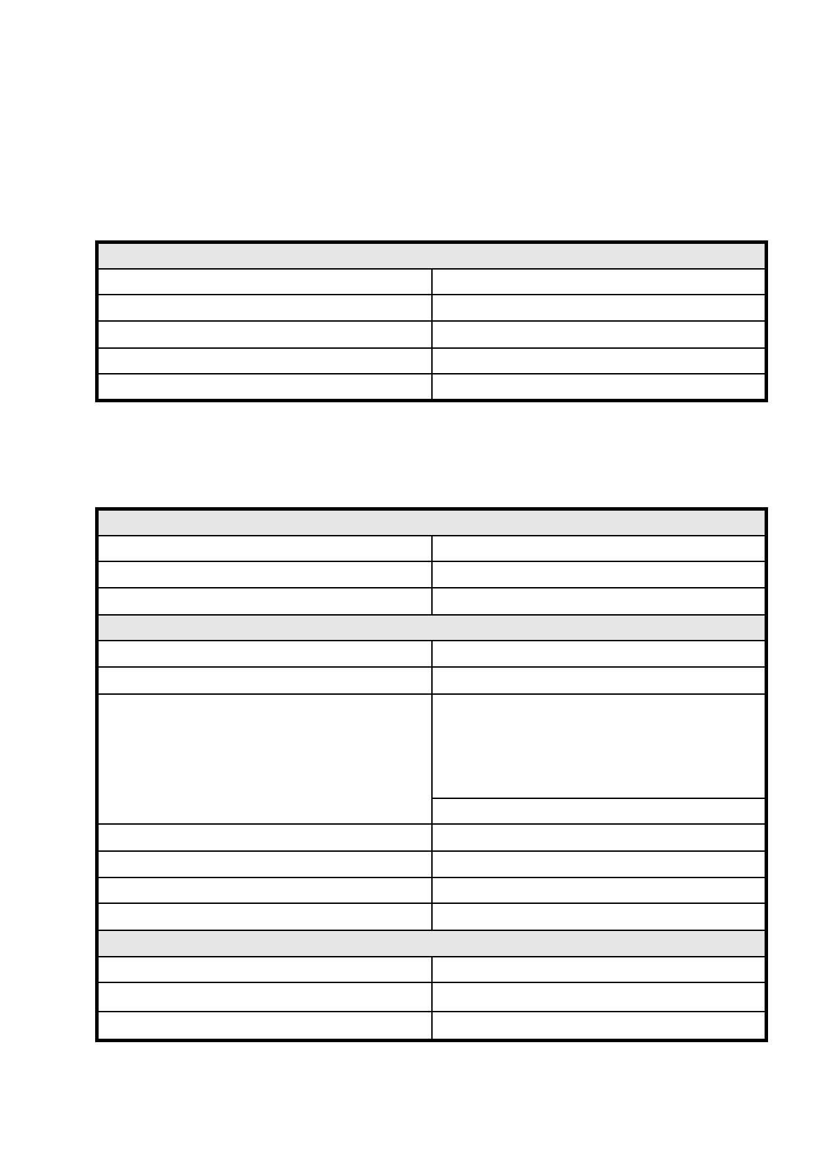
0.2.3 SIPLACE G
0.2.3.1 G Main Gantry
0.2.3.2 Gluing Unit
G main gantry
Drive D.C. servo motors
Path-measuring system Linear incremental scales
Resolution x / y axes 2.5
µ
m
Max. speed x axis 0.6 m/s
Max. speed y axis 0.6 m/s
Mini gantry
Drive D.C. servo motors
Path-measuring system Incremental shaft encoder
Resolution kx/ ky axis 17.5 µm
Gluing head
Placement force z axis < 6 N
Z axis stroke 16 mm
Glue types which can be used
Heraeus PD 922/PD944
Heraeus PD 86000 2SPA
Heraeus PD 911
Loctite 3609
Amicon D125 F3/D125 FDR
Please consult AUT 5 before using other glue types
Dispensing volume 0.02 mm³ to 2.0 mm³
Gluing sizes 20
Spacers 0.1 / 0.15 / 0.2 / 0.25 / 0.30 mm
Needle diameter 0.3 / 0.44 / 0.6 mm
Adhesive temperature regulator
Range of settings (
T
) 15.5°C to 40°C
Permissible ambient temperature (
T
U
)
15°C to 35°C
Control range
T
U
-8°C <
T
<
T
U
+ 12°C
0 Introduction SIPLACE 80S/F/G User’s Manual
0.2 Technical Data Edition 07/97 from Software Version SR.010.xx
0 - 18
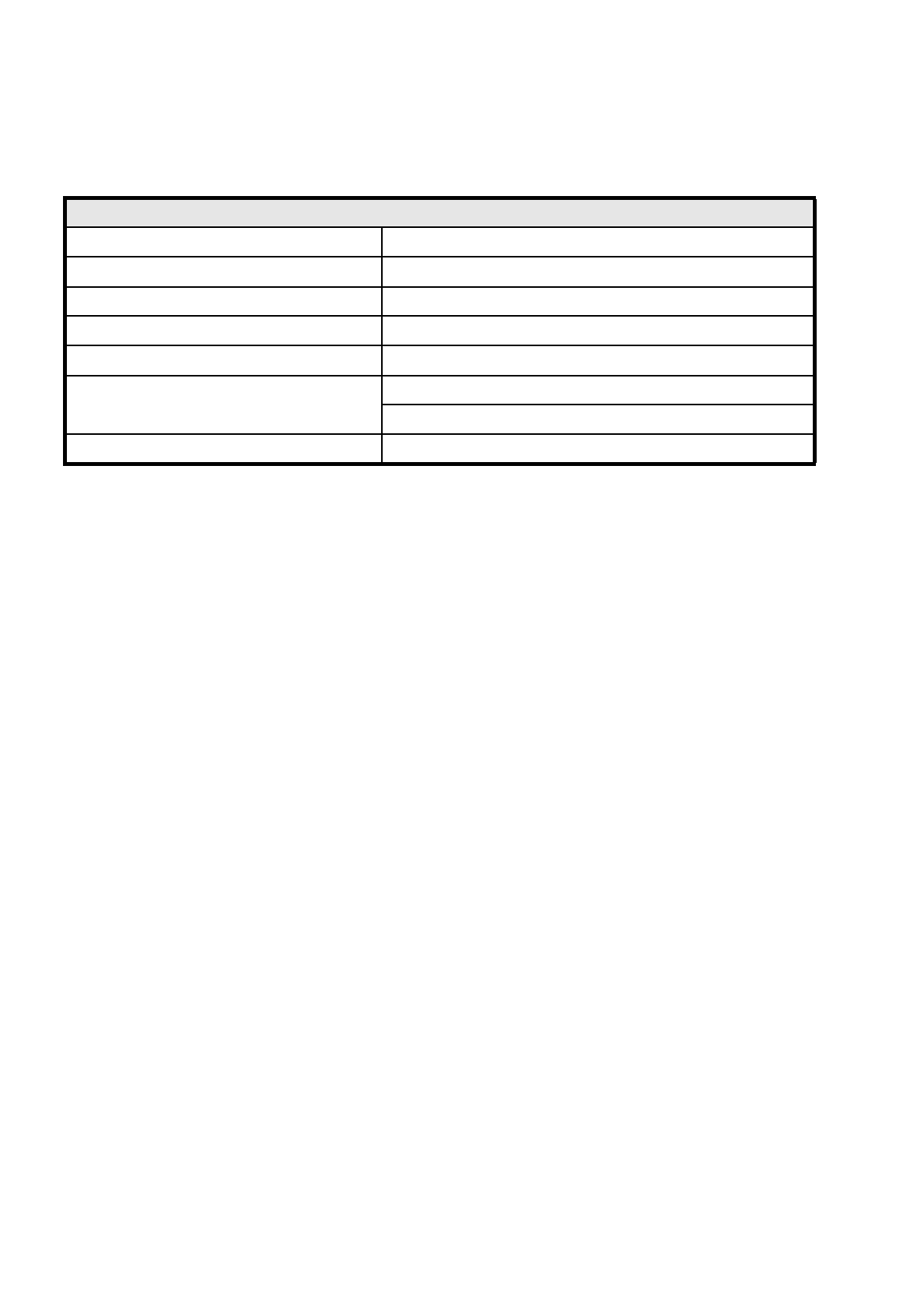
0.2.3.3 Boards (G)
0.2.3.4 Interfaces
0.2.1.5 Interfaces 80S
Boards
Boards (PCB) transport system In-line transport with width adjustment
PCB format 50 mm x 50 mm to 460 mm x 460 mm with PCB buffer
Component-free guide edge of the board 3 mm
Min. PCB thickness 0.5 mm
Max. PCB thickness 4.5 mm
Max. PCB warpage
Upwards : 4.5 mm less PCB thickness
Downwards: 0.5 mm plus PCB thickness
PCB change time 2.5 sec.
SIPLACE 80S/F/G User’s Manual 0 Introduction
Edition 07/97 from Software Version SR.010.xx 0.2 Technical Data
0 - 19
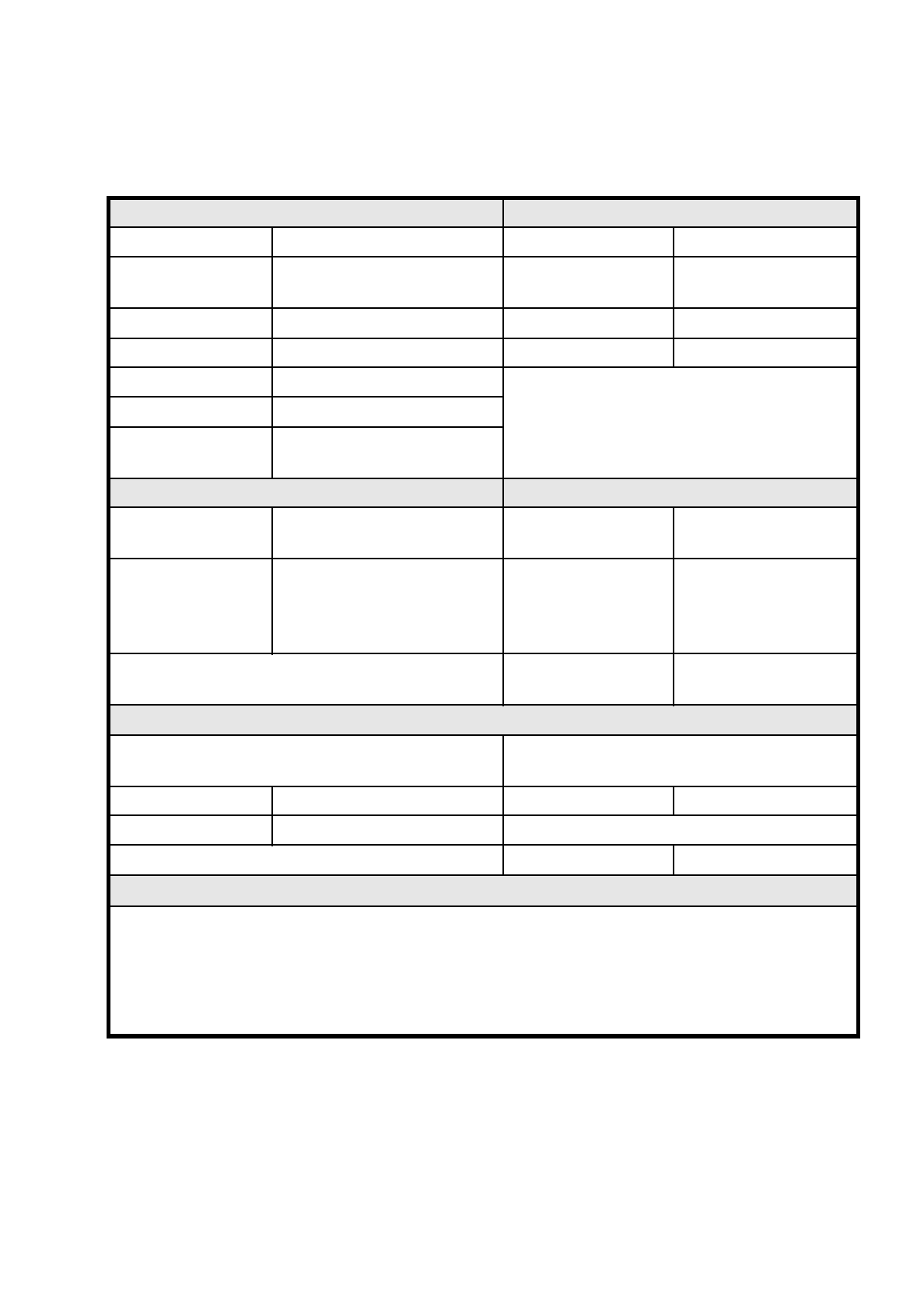
0.2.3.5 Connection and Installation Data G
Connection and Installation requirements Machine dimensions
System voltage 230/400V ± 10 % (50/60 Hz) Weight base module 1500 kg
System voltage
opt. e.g. for USA
110/208 V ± 10 % (50/60 Hz) Height with warning light 1836 mm
Total connected load 5 kVA Length 1587 mm
Total output 5 kW Width 2425 mm
Fuse protection 3 x 16 A
Compressed air supply At least 6 bar 400 NL/min.
Machine footprint
Permissible surface load
> 1 t/m²
Permissible environmental influences Machine control
Room temperature Between 15°C and 35°C Control computer
PC 386,
RMOS operating system
Air humidity
30 to 75 % (on average not higher
than 45 %, so that under no cir-
cumstances will there be conden-
sation in or on the machine
Machine control
SIMICRO
Input / output control
Axis controller
Siemens axis controller
boards (digital)
Compressed air specification
Max. particle size by density, based on ISO/DIS 8573-1
(Class 1)
Maximum oil content
Class 1
Particle size 0.1 µm Particle density 0.01 mg/m³
Particle density 0.1 mg/m³ Pressure dewpoint Class 4
Dewpoint + 3°C
Noise emission values specified in accordance with DIN 45 649-1
Emission value at a workstation (L
pAc
) 70 dB (A)
DIN EN ISO 11204 (i)
Sound power level (L
WAc
) 84 dB (A)
E-DIN EN ISO 3744 (i)
353-9217