00191025-01.pdf - 第235页
SIPLACE 80S/F/G User’s Manual 7 Vision Systems Edition 07/97 from S oftware Version SR.010.xx 7.5 Teaching the Fiducial Line engi neer 7 - 43 7.5.3.5 Option “Test fiducial” NOTE The opti on “Test fiducial” is only ac tiv…
7 Vision Systems SIPLACE 80S/F/G User’s Manual
7.5 Teaching the Fiducial Edition 07/97 from Software Version SR.010.xx
7 - 42 Line engineer
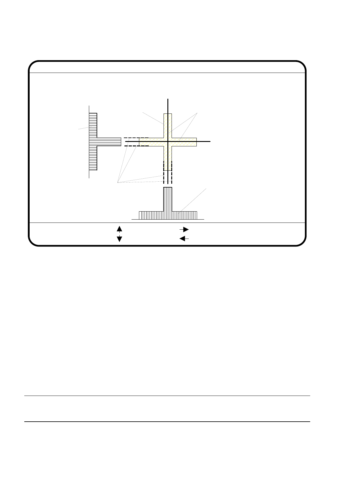
Fig. 7.5.9
The function “Center fiducial” determines by software the center of the fiducial. The parameters for this func-
tion - that is, the edges of the fiducial structure - can be selected in dialog mode. The system places, as a sug-
gestion, edge line markings at the possible edge positions.
●
With the arrow keys you can shift the current edge line marking provided in the header line.
●
With “RETURN” you can accept the position of the suggested edge line marking or of one which has been
shifted. The system then indicates the next edge line marking for acceptance. The sequence in which you
are asked is “fiducial edge left”, “fiducial edge right”, “fiducial edge up” and finally “fiducial edge dn”. This
notation appears in the header line.
The result of the fiducial centering is indicated by a crosshair. The x and y offset values of the center of the
fiducial are entered into the fiducial data field.
●
With the “ESC” key you can quit the option and return to the menu “Teach fiducial”.
PLEASE NOTE:
An incorrectly centered fiducial will cause a placement offset.
Edge ok
Fiducial No. = 8 Edge = left
Ret :
Center fiducial
: up
: dn
: right
: left
Fiducial
Result: Centering crosshair
Edge line markings to be shifted
via cursor keys
Row profile of fiducial
Column profile
of fiducial
SIPLACE 80S/F/G User’s Manual 7 Vision Systems
Edition 07/97 from Software Version SR.010.xx 7.5 Teaching the Fiducial
Line engineer 7 - 43
7.5.3.5 Option “Test fiducial”
NOTE
The option “Test fiducial” is only activated if
— you have already entered a fiducial number and
— a definition already exists for the number selected.
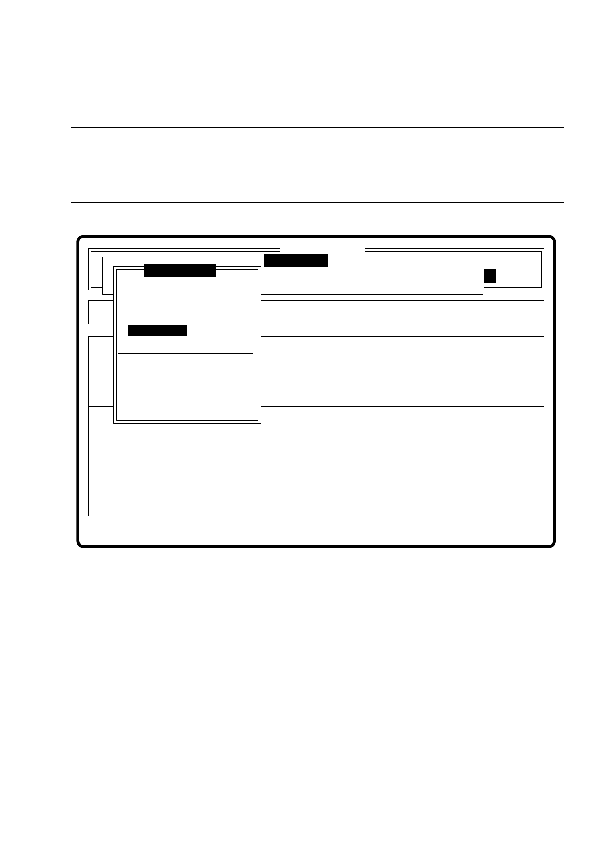
Fig. 7.5.10
The dimensions of the pattern structure and search area are stored in the station computer. These variables
are required for the calculation of the traverse paths for the corner test. The centering offsets of a centering
operation which may have been carried out previously is also taken into account in the calculation of the
traverse paths. After this
–
the test sequence is displayed via the video image,
–
the header line is displayed with the option, the fiducial number and the quality factor.
–
in the footer line the control panels and command sequences are displayed and a test procedure initiated
which determines the quality factor of the fiducial.
●
By pressing the “RETURN” key you can repeat the test procedure.
●
With the arrow keys you can change the gantry position. By entering the numbers 1 ... 6 you can change
the increment.
Error
State
Action
Test fiducial
Single functions
:
:
:
SI80 V 10.x
Vision system
Vision system
Setup:
Rüstung:
BE - Zuführung
Cluster:
Vision system
Version: 2133
Enter fiducial number
New fiducial
Edit fiducial
Center fiducial
Test fiducial
Move x/y axes
PCB to center conveyor
PCB to output conveyor
Choose gantry
Display errors
Teach fiducial
7 Vision Systems SIPLACE 80S/F/G User’s Manual
7.5 Teaching the Fiducial Edition 07/97 from Software Version SR.010.xx
7 - 44 Line engineer
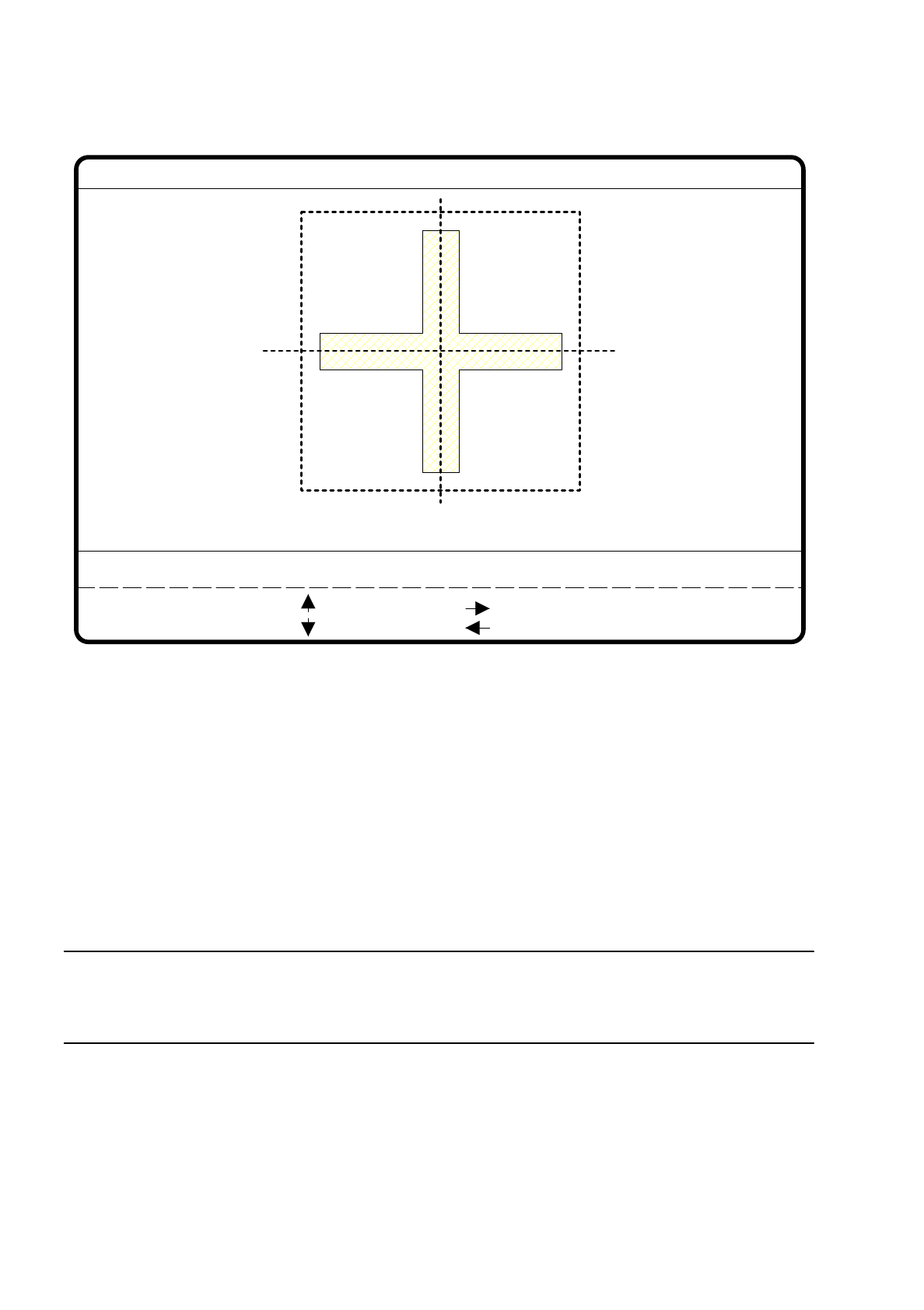
Fig. 7.5.11
The PCB camera travels to the 4 corners of the search area and executes in each case a measurement com-
mand. For each executed measurement command the machine controller receives the fiducial quality from the
vision evaluation unit (MVS). The worst value (worst case) of the tests is shown on the monitor in the header
line. The quality level ranges from
–
0 = bad to
–
100 = very good
and should not fall below value of 40 for the fiducial and the ink dot. Otherwise we recommend you select
another fiducial.
NOTE
Here compare also the relationship between uniqueness and fiducial quality as described in Section 7.5.3.2
Option “New fiducial”.
Fiducial No. = 8 Quality fact. = 70Test fiducial
test
1..6 : x/y step
Ret :
x/y step width = ...
: x axis +
: x axis -
: y axis +
: y axis -