00191025-01.pdf - 第272页
7 Vision Systems S IPLACE 80S/F/G User’s Manual 7.6 Test Component Edition 07/97 from Software Version S R.010.xx 7 - 80 Line engine er Cross: White : measur ed ball ca ndidates which are de fined in the G F file. Cross-…

SIPLACE 80S/F/G User’s Manual 7 Vision Systems
Edition 07/97 from Software Version SR.010.xx 7.6 Test Component
Line engineer 7 - 79
Cross-hairs:
White: results of position recognition -> x, y, angle
Star:
White: center of the component -> position
Synthetic representation of the model at the lefthand edge of the video screen:
Image: Model in pixel resolution
Points marked with a red + sign:
outside the circle:
Contrast < 0, ball is darker than the background
inside the circle:
Contrast > 0, ball is brighter than the background
Points marked with a yellow – sign:
The separation between “+” and “–” characters represents
the radius tolerance.
2. Ball-Driven Mode
See
Section 7.6.5.2 from page 7 - 95
for a definition of the measuring methods.
The method works with high precision and is thus suitable for precisely determining the position of all defined
balls.
Ball-driven mode as a precise search follows grid-driven mode.
The measuring methods can be recognized by
–
the synthetic representation of the model in pixel resolution at the lefthand edge of the video screen
–
there being a window around each ball (separate window) or
–
depending on memory, there being one window over the entire component or one defined row of balls
(combined window).
Procedure:
All of the balls defined in the GF file are gauged. The selection of window mode will be based on geometrical
criteria:
–
If the distance between two balls is low (< 2 x ball diameters), the "combined" window mode will be pre-
ferred.
–
If the ball separation is larger, the "separate" window mode will be chosen. The default mode is the sepa-
rate window.
Window:
Dark-blue: over one ball in each case (separate window)
over one row or all of the balls (combined window)

7 Vision Systems SIPLACE 80S/F/G User’s Manual
7.6 Test Component Edition 07/97 from Software Version SR.010.xx
7 - 80 Line engineer
Cross:
White: measured ball candidates which are defined in the GF file.
Cross-hairs:
White: results of position recognition -> x, y, angle
Star:
White: Position of the component
Synthetic representation of ball model
In pixel resolution on the lefthand edge of the video screen
A description is provided under the heading "Grid-Driven Mode".
SIPLACE 80S/F/G User’s Manual 7 Vision Systems
Edition 07/97 from Software Version SR.010.xx 7.6 Test Component
Line engineer 7 - 81
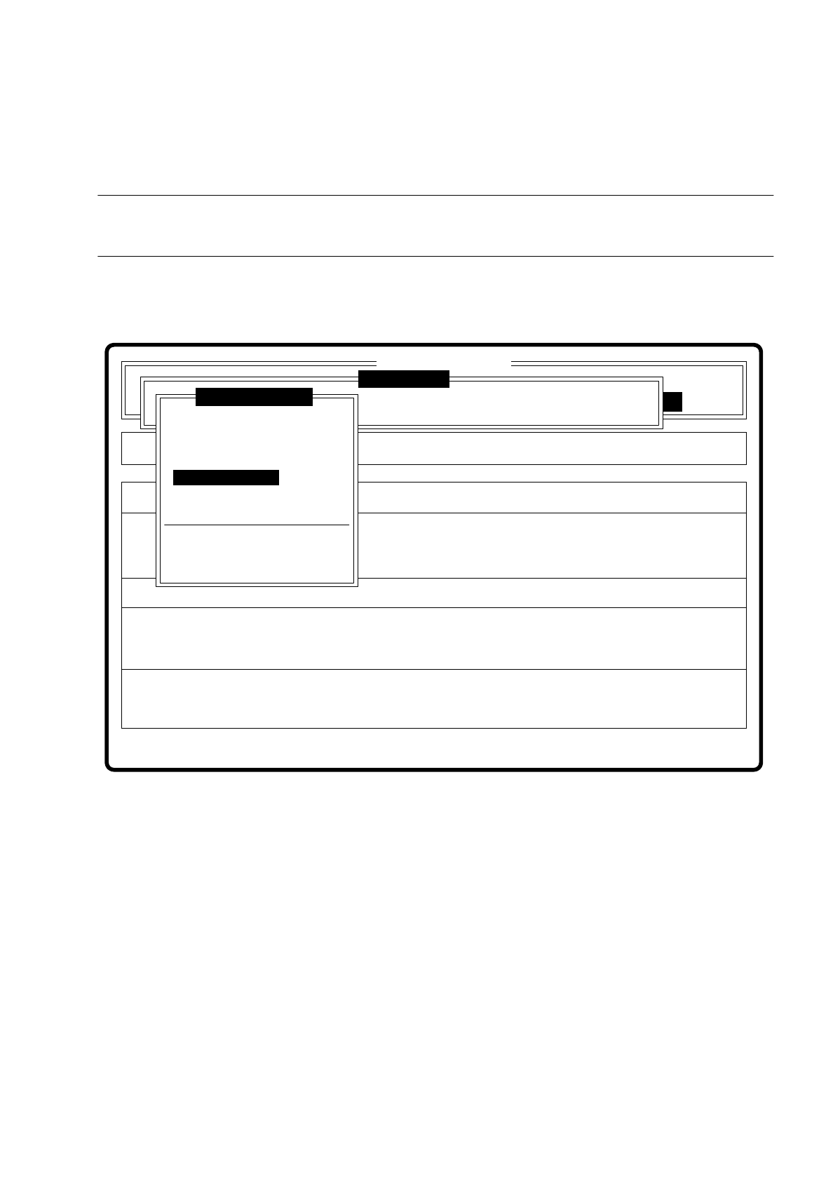
7.6.3.5 Option “Test component”
NOTE
This option can only be activated if a GF number has already been entered.
If a component is not optically centered, you have the choice of checking the centering procedure with this
option. The measurement result is presented visually on the screen; measurement results are not saved.
Fig. 7.6.11
When this function is activated the following actions are initiated:
–
The measuring procedure is activated.
–
The video image is displayed on the screen.
–
Top and bottom lines appear.
Error
State
Action
Check component step by step
Single functions
:
:
:
Cluster:
SI80 V 10.x
Vision system
Vision system
Vision system
Version: 2133
Setup:
Test component
Enter GF number
Pickup component
Display component
Measure component
Test component
Edit GF data
Change measure mode
Refill
Display errors
Test output