00191025-01.pdf - 第282页
7 Vision Systems SIPLACE 80S /F/G User’s Manual 7.6 Test Component Edition 07/97 f rom Software Version SR.010.xx 7 - 90 Line engine er ● With the “RE TURN” key you can initiate the i ndividual measuremen t steps, which …
SIPLACE 80S/F/G User’s Manual 7 Vision Systems
Edition 07/97 from Software Version SR.010.xx 7.6 Test Component
Line engineer 7 - 89
●
Parameters of the color image (5 sections)
–
10 parameters “IN” values
–
10 parameters “OUT” values
The parameters are stored in the GF file in the line computer. When requested, the GF file is sent to the sta-
tion computer. It is then converted and transferred to the MVS computer.
If you change a parameter, it will be entered in the GF file, the GF file converted and then loaded into the MVS
computer.
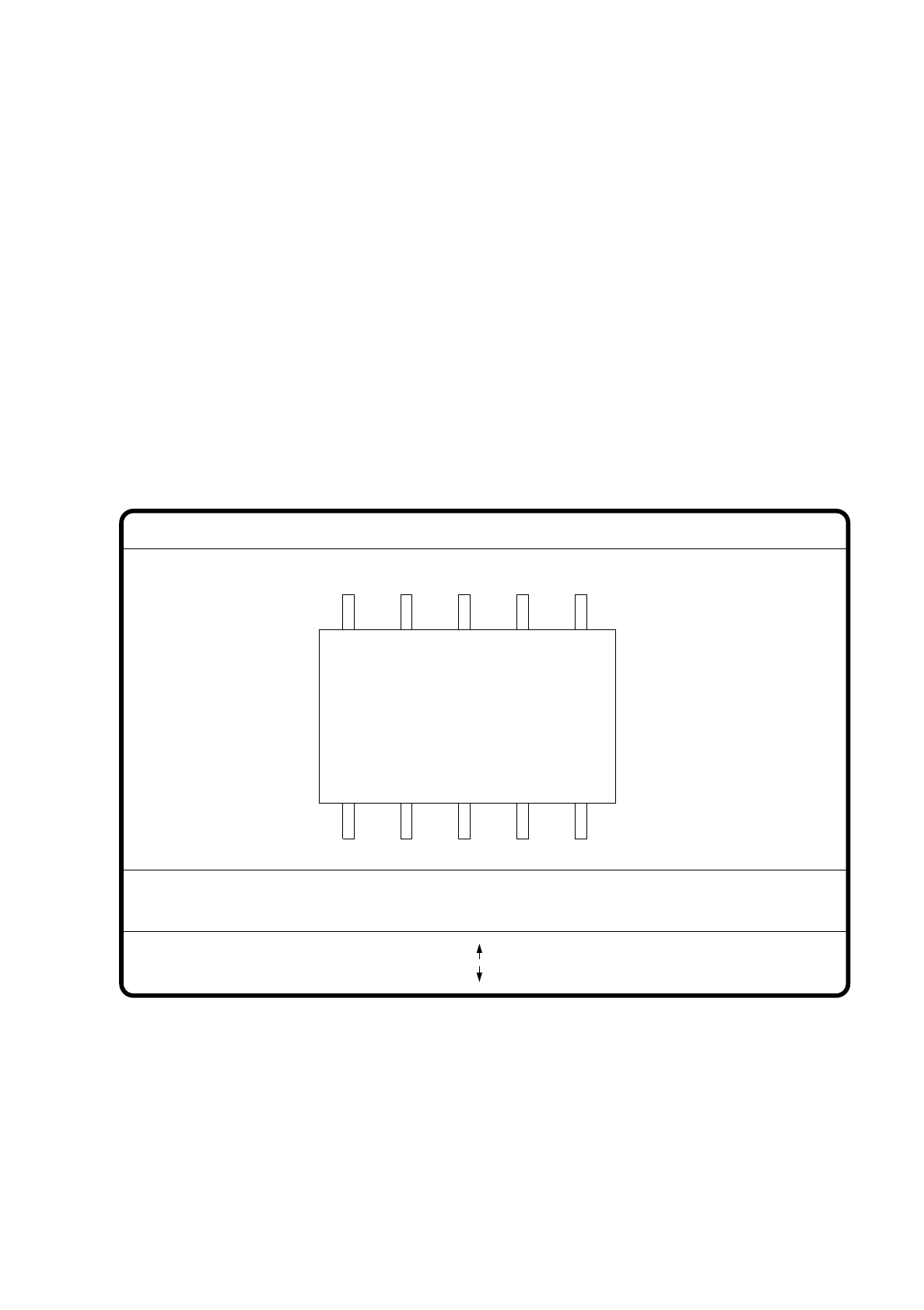
7.6.4.1 Option “Pin dimension”
With this option you can change the optical pin width and length. In addition the pin contrast can also be
changed should the imaging reduction mean that the pins cannot be easily recognized.
Fig. 7.6.18
●
With the Tab key you can select the pin model.
●
With the space bar you can select the pin side.
●
With > and < you raise or lower the pin contrast.
●
With the arrow keys you can change the pin width and length. The component is displayed on the video
screen in its external contours and with the up-dated geometric pin data.
GF No. = 5
Pin dimension
>: contrast +
<: contrast -
opt. l.[mm] = ...
opt. w.[mm] = ...
Pin side =
Pin definition = 1..n
RET: Test component
Tab: Pin model
Blank: Pin side
Pin contrast =
: larger
: smaller
7 Vision Systems SIPLACE 80S/F/G User’s Manual
7.6 Test Component Edition 07/97 from Software Version SR.010.xx
7 - 90 Line engineer
●
With the “RETURN” key you can initiate the individual measurement steps, which form part of the mea-
surement conditions for the specified component.
●
With “ESC” you can abort the option, even if not all measurement steps have yet been executed. You are
returned to the menu “Edit GF data”.
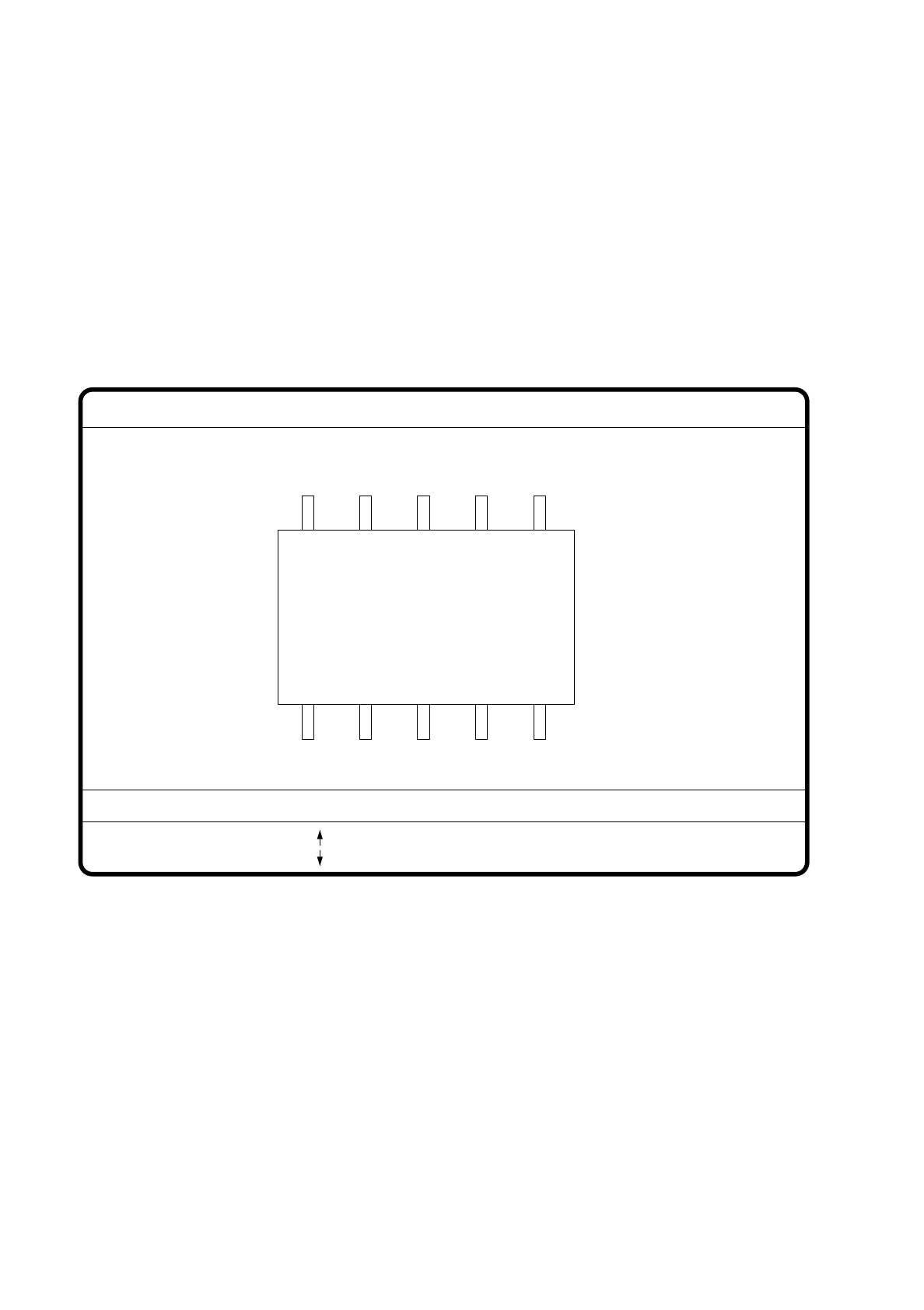
7.6.4.2 Option “Package dimension”
You have the possibility of changing the optical package width and length if the effect of imaging reduction is
excessive. This effect occurs predominantly with cylindrical components.
Fig. 7.6.19
●
With the arrow keys you can change the length and width of the component. The current geometric data
are displayed.
●
With the space bar you can toggle between the sides of the component.
●
With “RETURN” you can initiate the individual measurement steps, which are specified in the measure-
ment conditions.
●
With “ESC” you may quit the option.
GF No. = 5
: larger
: smaller
RET: Test component
Blank: Pack. side
Pack. side = opt. l.[mm] = ... opt. w.[mm] = ...
Pin dimension
SIPLACE 80S/F/G User’s Manual 7 Vision Systems
Edition 07/97 from Software Version SR.010.xx 7.6 Test Component
Line engineer 7 - 91
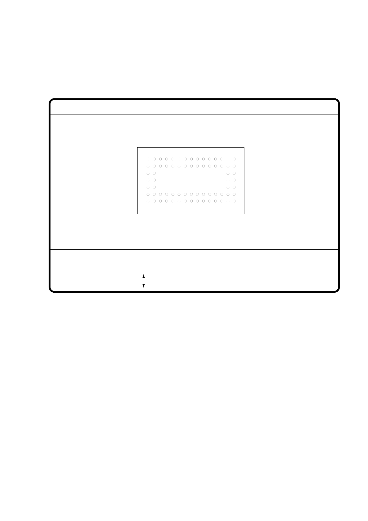
7.6.4.3 Option "Ball Image"
With this option you can change the ball model description in the 80F machine.
Fig. 7.6.20
●
Use the tabulator key to select the ball model.
●
Use the space bar to select the radius type - inside or outside radius.
●
Use the arrow keys to enlarge or reduce the inside or outside radius of the solder balls. The solder balls will
appear in their geometrical dimensions as a pixel image at the lefthand edge of the video screen.
●
The value of the inside radius determines the shape of the ball:
–
If the inside radius is equal to 0, the shape of the ball will be a circle.
–
If the inside radius is greater than 0, the shape of the ball will be a doughnut.
●
With > or < you can increase or reduce the ball contrast.
●
With the “RETURN” key you can launch the individual measurement steps which are found in the mea-
surement conditions for the specified component.
●
With ESC you can quit this option even if not all of the measurement steps have been carried out.
You will be returned to the menu "Change GF data".
GF no. = 5
Ball image
: larger
: smaller
RET: Test comp.
Tab: Ball model
Rad. i.[mm]
> : Contrast +
< : Contrast
Contrast i.
Ball model = 1
Rad. e.[mm] Contrast e.
Rad. type: intern/extern
Blank: Radius type
= 0.500
= 1.500
= 20
= 10