00191025-01.pdf - 第284页
7 Vision Systems SIPLACE 80S /F/G User’s Manual 7.6 Test Component Edition 07/97 f rom Software Version SR.010.xx 7 - 92 Line engine er 7.6.4.4 Option “Illumination” On sele cting this option the video im age for i llumi…
SIPLACE 80S/F/G User’s Manual 7 Vision Systems
Edition 07/97 from Software Version SR.010.xx 7.6 Test Component
Line engineer 7 - 91
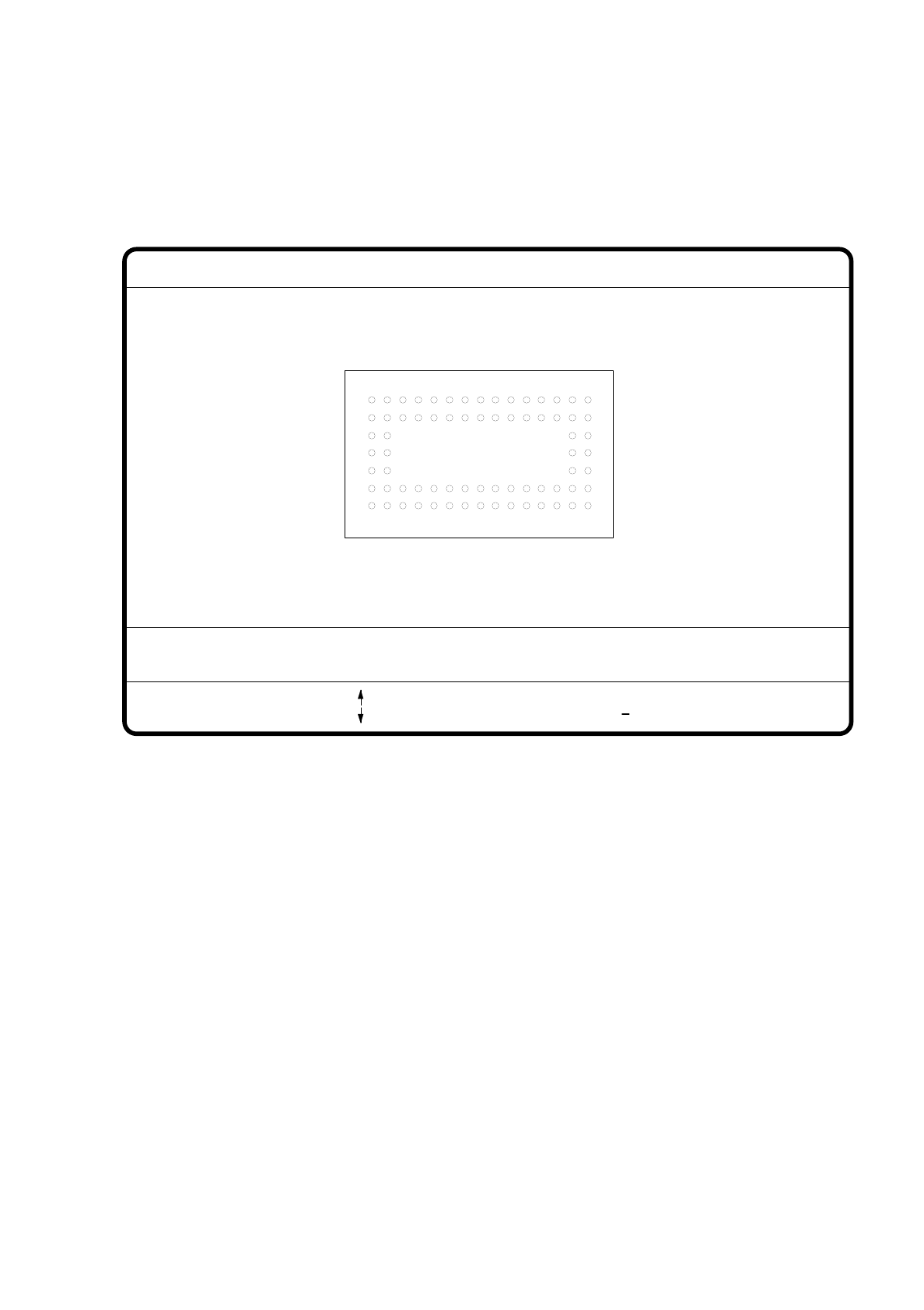
7.6.4.3 Option "Ball Image"
With this option you can change the ball model description in the 80F machine.
Fig. 7.6.20
●
Use the tabulator key to select the ball model.
●
Use the space bar to select the radius type - inside or outside radius.
●
Use the arrow keys to enlarge or reduce the inside or outside radius of the solder balls. The solder balls will
appear in their geometrical dimensions as a pixel image at the lefthand edge of the video screen.
●
The value of the inside radius determines the shape of the ball:
–
If the inside radius is equal to 0, the shape of the ball will be a circle.
–
If the inside radius is greater than 0, the shape of the ball will be a doughnut.
●
With > or < you can increase or reduce the ball contrast.
●
With the “RETURN” key you can launch the individual measurement steps which are found in the mea-
surement conditions for the specified component.
●
With ESC you can quit this option even if not all of the measurement steps have been carried out.
You will be returned to the menu "Change GF data".
GF no. = 5
Ball image
: larger
: smaller
RET: Test comp.
Tab: Ball model
Rad. i.[mm]
> : Contrast +
< : Contrast
Contrast i.
Ball model = 1
Rad. e.[mm] Contrast e.
Rad. type: intern/extern
Blank: Radius type
= 0.500
= 1.500
= 20
= 10
7 Vision Systems SIPLACE 80S/F/G User’s Manual
7.6 Test Component Edition 07/97 from Software Version SR.010.xx
7 - 92 Line engineer
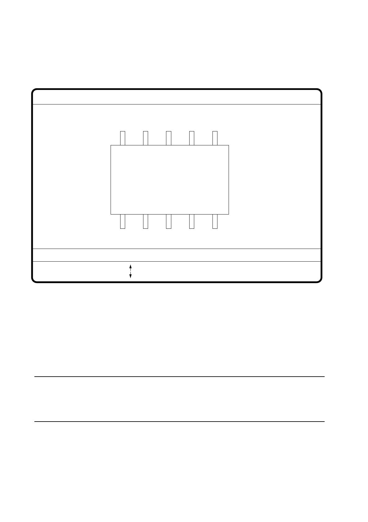
7.6.4.4 Option “Illumination”
On selecting this option the video image for illumination control and adjustment is displayed.
Fig. 7.6.21
●
With the arrow keys you can increase or decrease the brightness of the LED rows in the component cam-
era system used for illuminating the component. The brightness level can be set to one of 256 steps, with
255 being the maximum value.
●
With the space bar switch the step size for changing brightness from 1 to 10
µ
m and back.
●
Use the tab key to choose between the two lighting levels: steep camera illumination (top row of LEDs) or
flat camera illumination (bottom row of LEDs) at the revolver head. With the IC head there are three illumi-
nation levels to choose from (see Section 7.9.2.2).
NOTE
Please refer to Section 7.7.6 ’Setting the Components Illumination at the Revolver Head Camera’, on
page 7 - 104 for information on selecting the illumination parameters and to Section Section 7.7.7 ’Setting
the Components Illumination at the IC Head Camera’, on page 7 - 109.
●
With the “RETURN” key you can initiate the individual measurement steps, which were entered in the mea-
surement conditions.
●
With “ESC” you may quit the option. You then return to the starting menu “Edit GF data”.
GF No. = 5
Illumination
: Brightness up
: Brightness down
RET: Test component
Tab: Illumination
Illuminat. = plane/steep
Brightness = 0 ... 255
Blank: Step width
Step width =
SIPLACE 80S/F/G User’s Manual 7 Vision Systems
Edition 07/97 from Software Version SR.010.xx 7.6 Test Component
Line engineer 7 - 93
7.6.4.5 Option “Program transform”
This option is analogous to the option “Program transform 5” in Section 7.5.5.2 and there described.
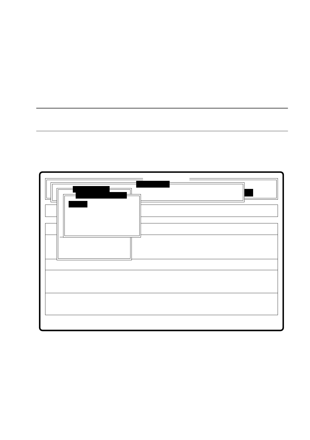
7.6.5 Menu “Change measure mode”
NOTE
The option can only be activated if a GF number has previously been entered.
In the sensor-specific part of the GF data (see Section 7.6.4) there is a data structure with measurement con-
ditions for the components. In this menu you can manipulate these measurement conditions. The menu
options are primarily intended for creating one's own user-specific GF files outside the standard GF file.
Fig. 7.6.22
The menu offers you the possibility of
–
selecting and activating a specific method of measurement or combination of several methods
–
deactivating measurement methods, and
–
modifying the hex parameters corresponding to each method of measurement.
Error
State
Action
Change measure mode Size
Rüstung:
Maschinenoptionen Single functions
Softwareoptionen
:
:
:
BE - Zuführung
Cluster:
SI80 V 10.x
Vision system
Vision system
Version: 2133
Setup:
Marke teachen
Test component
Refill
Display errors
Test output
Mess-Mode ändern
GF-Nr. eingeben
BE abholen
BE darstellen
BE prüfen
GF-Daten ändern
BE messen
Change measure mode
Row
Lead
Corner
Size
Grid
Ball