00191025-01.pdf - 第285页
SIPLACE 80S/F/G User’s Manual 7 Vision Systems Edition 07/97 from S oftware Version SR.010.xx 7.6 Test Co mponent Line engi neer 7 - 93 7.6.4. 5 O ption “Pro gram tran sform” This opti on is analog ous to the option “Pr …
7 Vision Systems SIPLACE 80S/F/G User’s Manual
7.6 Test Component Edition 07/97 from Software Version SR.010.xx
7 - 92 Line engineer
7.6.4.4 Option “Illumination”
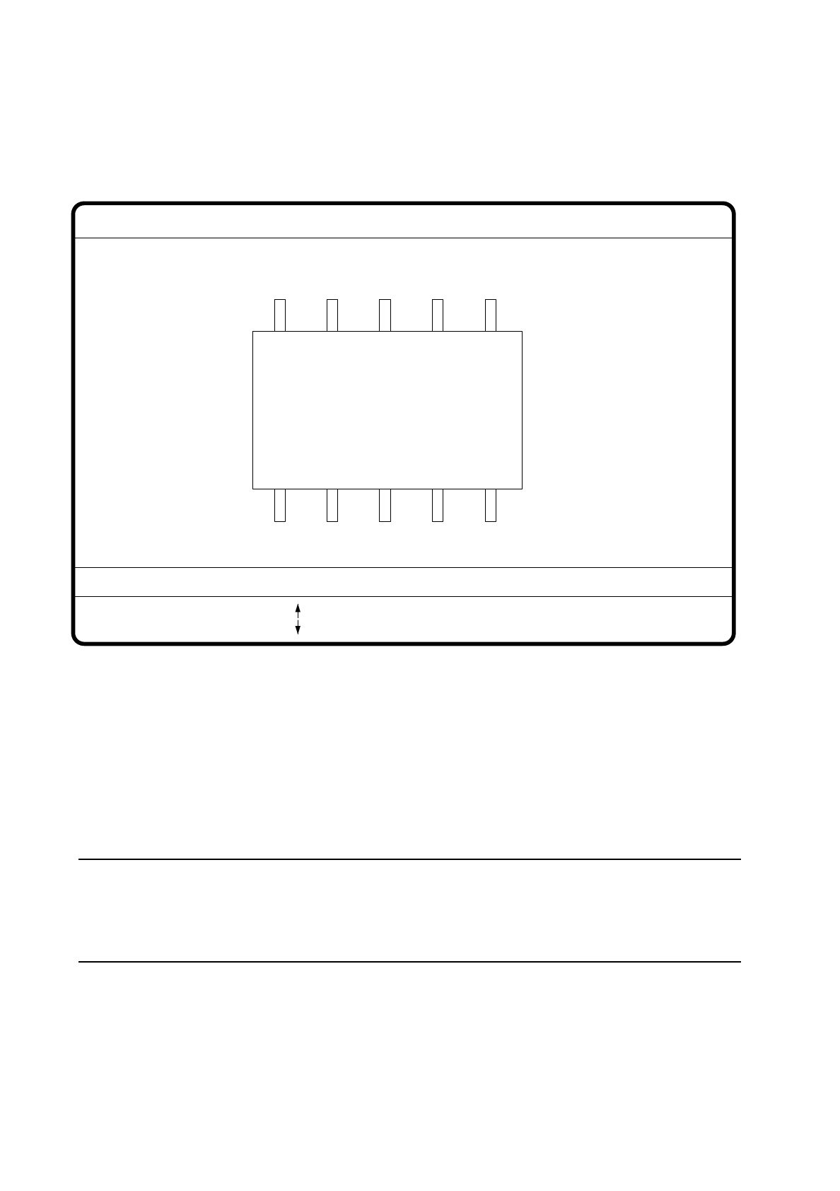
On selecting this option the video image for illumination control and adjustment is displayed.
Fig. 7.6.21
●
With the arrow keys you can increase or decrease the brightness of the LED rows in the component cam-
era system used for illuminating the component. The brightness level can be set to one of 256 steps, with
255 being the maximum value.
●
With the space bar switch the step size for changing brightness from 1 to 10
µ
m and back.
●
Use the tab key to choose between the two lighting levels: steep camera illumination (top row of LEDs) or
flat camera illumination (bottom row of LEDs) at the revolver head. With the IC head there are three illumi-
nation levels to choose from (see Section 7.9.2.2).
NOTE
Please refer to Section 7.7.6 ’Setting the Components Illumination at the Revolver Head Camera’, on
page 7 - 104 for information on selecting the illumination parameters and to Section Section 7.7.7 ’Setting
the Components Illumination at the IC Head Camera’, on page 7 - 109.
●
With the “RETURN” key you can initiate the individual measurement steps, which were entered in the mea-
surement conditions.
●
With “ESC” you may quit the option. You then return to the starting menu “Edit GF data”.
GF No. = 5
Illumination
: Brightness up
: Brightness down
RET: Test component
Tab: Illumination
Illuminat. = plane/steep
Brightness = 0 ... 255
Blank: Step width
Step width =
SIPLACE 80S/F/G User’s Manual 7 Vision Systems
Edition 07/97 from Software Version SR.010.xx 7.6 Test Component
Line engineer 7 - 93
7.6.4.5 Option “Program transform”
This option is analogous to the option “Program transform 5” in Section 7.5.5.2 and there described.
7.6.5 Menu “Change measure mode”
NOTE
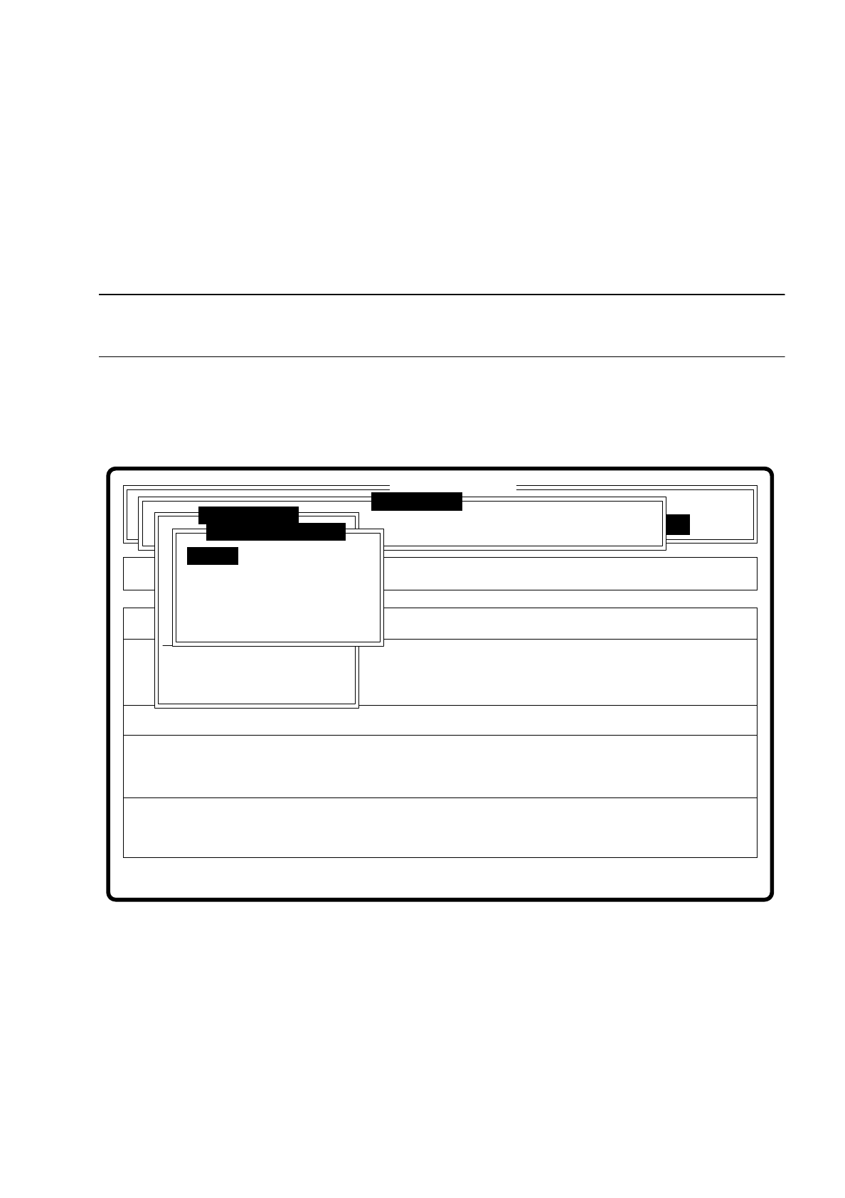
The option can only be activated if a GF number has previously been entered.
In the sensor-specific part of the GF data (see Section 7.6.4) there is a data structure with measurement con-
ditions for the components. In this menu you can manipulate these measurement conditions. The menu
options are primarily intended for creating one's own user-specific GF files outside the standard GF file.
Fig. 7.6.22
The menu offers you the possibility of
–
selecting and activating a specific method of measurement or combination of several methods
–
deactivating measurement methods, and
–
modifying the hex parameters corresponding to each method of measurement.
Error
State
Action
Change measure mode Size
Rüstung:
Maschinenoptionen Single functions
Softwareoptionen
:
:
:
BE - Zuführung
Cluster:
SI80 V 10.x
Vision system
Vision system
Version: 2133
Setup:
Marke teachen
Test component
Refill
Display errors
Test output
Mess-Mode ändern
GF-Nr. eingeben
BE abholen
BE darstellen
BE prüfen
GF-Daten ändern
BE messen
Change measure mode
Row
Lead
Corner
Size
Grid
Ball
7 Vision Systems SIPLACE 80S/F/G User’s Manual
7.6 Test Component Edition 07/97 from Software Version SR.010.xx
7 - 94 Line engineer
7.6.5.1 Dialog Boxes "Size", "Row", "Corner", "Lead", "Grid" and "Ball"
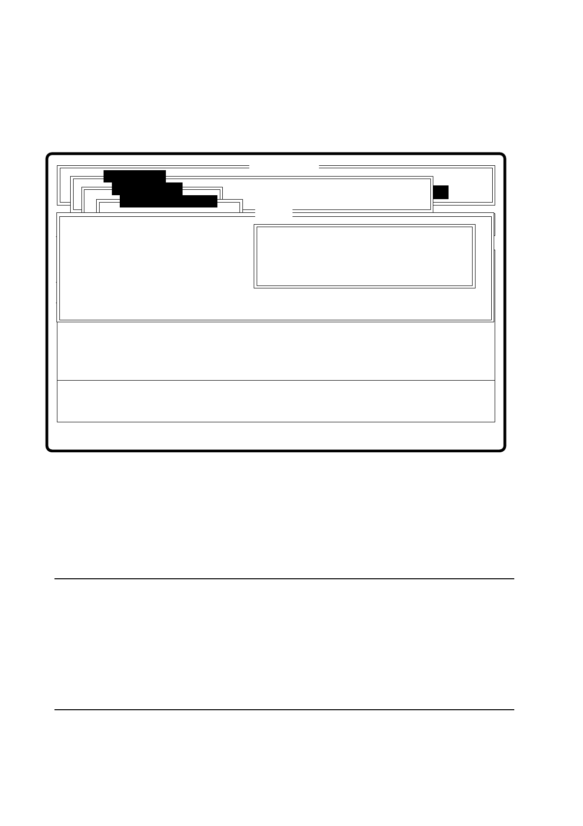
After a menu item has been selected the corresponding dialog window - "Size", "Row", "Corner", "Lead",
"Grid" or "Ball" opens. The "Corner" dialog window is shown as an example.
Fig. 7.6.23
●
With the Tab key you can toggle between option box and input box.
●
Use the arrow keys to position the cursor in the appropriate dialog box.
●
Use the space bar to mark in the option field the measurement method you have chosen. A cross is dis-
played to show that the option has been selected.
●
In the input field you can change the hex values of the measurement method and thus cater for the require-
ments of special components.
NOTE
Entering hex values presupposes considerable knowledge in measurement methodology. Explanatory
material in this connection goes beyond the scope of this operating manual. A detailed description will be
found, however, in the "MVS/EDA1 Application Manual". In this connection may we refer you in particular
to Sections III.7 "Electronic Device Alignment and Inspection: Implementation" and VII.4 "Electronic
Device Alignment and Inspection".
If you do intend to alter the hex values, then please contact the vision system development group and after
you have discussed the matter with them, enter the bit-coded hex values.
Error
State
Action
Change measure mode Corner
Rüstung:
Single functions
:
:
:
Nutzen:
SI80 V 10.x
Vision system
Vision system
Rüstung.
Test component
BE abholen
Size
Row
Lead
Corner
Change measure mode
( ) Corner driven
Esc: abort Blank: select Tab: change wind
CORNER P1 [ Hex ] :
CORNER P2 [ Hex ] :
CORNER P3 [ Hex ] :
CORNER P4 [ Hex ] :
CORNER P5 [ Hex ]:
Ret: input
Corner