00191025-01.pdf - 第288页
7 Vision Systems S IPLACE 80S/F/G User’s Manual 7.6 Test Component Edition 07/97 from Software Version S R.010.xx 7 - 96 Line engine er ● Lead-driven (pin inspect ion) With this method th e informatio n is obtaine d from…

SIPLACE 80S/F/G User’s Manual 7 Vision Systems
Edition 07/97 from Software Version SR.010.xx 7.6 Test Component
Line engineer 7 - 95
●
With “RETURN” close the dialog box. The modified measurement conditions are written to the GF file in
the station computer.
●
With “ESC” you can abort the dialog box without accepting data, then returning to the menu “Test compo-
nent”.
7.6.5.2 Information on the Measurement
With conventional components with lead connections, component centering is essentially based on four mea-
suring methods which aim at determining the position (x, y coordinates,
Φ
= angle of rotation) of the compo-
nent and the lead parameters:
–
Size-driven mode
–
Row-driven mode
–
Corner-driven mode
–
Lead-driven mode
For BGAs (Ball Grid Arrays) and flip chips new algorithms have been implemented for determining the position
(x, y coordinates,
Φ
= angle of rotation) of the component and the ball parameters (see also Section 7.6.3.4
Option “Measure component”):
–
Grid-driven mode
–
Ball-driven mode
Depending on your circumstances any method in this sequence can be omitted. But it is not possible to alter
their sequence.
Definition of the methods
●
Size-driven
This method was developed especially for small components. On the strength of the information on dimen-
sion parameters the position and rotation of small components is determined rapidly and reliably.
This procedure is very robust as regards defects such as color markings.
The size-driven method makes use of profile creation. It creates a profile either along the length
or
across
the width of the components. Whichever you selected can be marked in the option box with a cross. As
default the profile is always created for the longer side.
●
Row-driven
This method is based on the information for a pin row.
It is very fast and supplies approximate values for the coordinates and the angle of rotation of the compo-
nent.
●
Corner-driven (component inspection)
The measurement results provide precise information on the coordinates and rotation of the component,
the pin number, the spacing and of the row offset.
This method is not sensitive to variations in pin dimensions.
7 Vision Systems SIPLACE 80S/F/G User’s Manual
7.6 Test Component Edition 07/97 from Software Version SR.010.xx
7 - 96 Line engineer
●
Lead-driven (pin inspection)
With this method the information is obtained from examining each individual pin.
The following combinations of methods are:
–
Size-driven — corner-driven — lead-driven (see table in Section 7.6.3.5) or
–
Row-driven — corner-driven — lead-driven (see table in Section 7.6.3.5)
●
Grid-driven
(Component inspection with the 80F machine)
The measurement results provide information on the approximate coordinates and the approximate rota-
tion of the component. They also give an indication of the quality of measurement.
●
Ball-driven
(Determining the solder ball position with the 80F machine)
The measurement results provide precise information on the coordinates and the rotation of the compo-
nent. They also give information of the maximum ball offset and the quality of measurement.
7.6.5.3 Recommendations concerning the Optimum Sequence of Methods
In the following table recommendations are provided for the optimum sequence of methods for components:
These are the abbreviations used:
B = ball driven
C = corner driven
G = grid driven
L = lead driven
R = row driven
S = size driven
* (L) applies to irregularly shaped components with separate windows
Component Measurement Sequence
S R G C L B
MELF S C L
CHIP S C L
SOT S C L
S L
SOJC6 S C
SOJC14 R C
LCC R C (L)
PLCC R C (L)
QFP R C (L)
TAB R C (L) *)
BGA, Flip chip G B
SIPLACE 80S/F/G User’s Manual 7 Vision Systems
Edition 07/97 from Software Version SR.010.xx 7.7 Guidelines for Describing Package Forms
Line engineer 7 - 97
7.7 Guidelines for Describing Package Forms
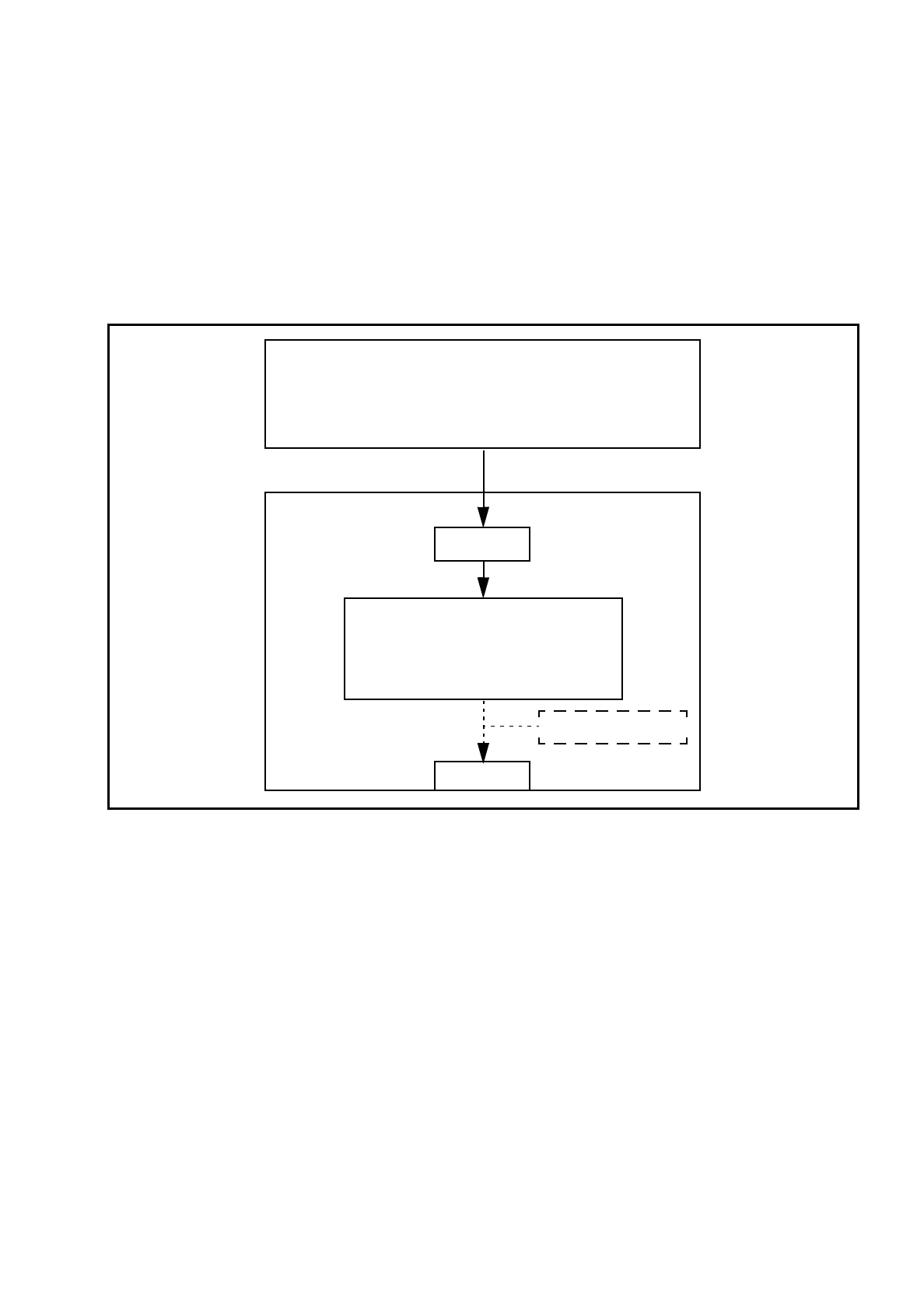
7.7.1 Transfer of Package Form Data and the Package Form Interpreter
If a package form is transferred to the station without an .SST file, the package form interpreter will make cer-
tain settings to enable the package form to be measured in accordance with the package form description.
Fig. 7.7.1 Transfer of package form data without package form manipulation
In SIPLACE 80 S-15/F3 automatic placement machines, the package form interpreter is located in the machine
controller. The communication module transfers the signals for controlling the lighting from the MC to the cameras.
Tasks of the Package Form Interpreter
–
Automatic selection of suitable measuring modes
–
Automatic selection of the measuring parameters
–
Automatic differentiation between cubic/not cubic
–
Automatic setting of the lighting
The package form interpreter processes standard components and automatically identifies special compo-
nents. Under certain circumstances, other components have to be post-processed. If the package form set-
tings have to be manipulated, these changes will be stored in the .SST file and transferred back to the line
computer.
GF manipulator
LC
●
Package form library
●
Describe package form & components
●
Assign nozzles
●
Select cameras
Hard disk
.OGF
Package form interpreter
●
Automatic selection of meas. modes
●
Automatic lighting selection
SC
MVS