00191025-01.pdf - 第289页
SIPLACE 80S/F/G User’s Manual 7 Vision Systems Edition 07/97 from S oftware Version SR.010.xx 7.7 Guidelines for Describing P ackage Forms Line engi neer 7 - 97 7.7 Gu idelines for Describi ng Packag e Forms 7.7.1 Transf…
7 Vision Systems SIPLACE 80S/F/G User’s Manual
7.6 Test Component Edition 07/97 from Software Version SR.010.xx
7 - 96 Line engineer
●
Lead-driven (pin inspection)
With this method the information is obtained from examining each individual pin.
The following combinations of methods are:
–
Size-driven — corner-driven — lead-driven (see table in Section 7.6.3.5) or
–
Row-driven — corner-driven — lead-driven (see table in Section 7.6.3.5)
●
Grid-driven
(Component inspection with the 80F machine)
The measurement results provide information on the approximate coordinates and the approximate rota-
tion of the component. They also give an indication of the quality of measurement.
●
Ball-driven
(Determining the solder ball position with the 80F machine)
The measurement results provide precise information on the coordinates and the rotation of the compo-
nent. They also give information of the maximum ball offset and the quality of measurement.
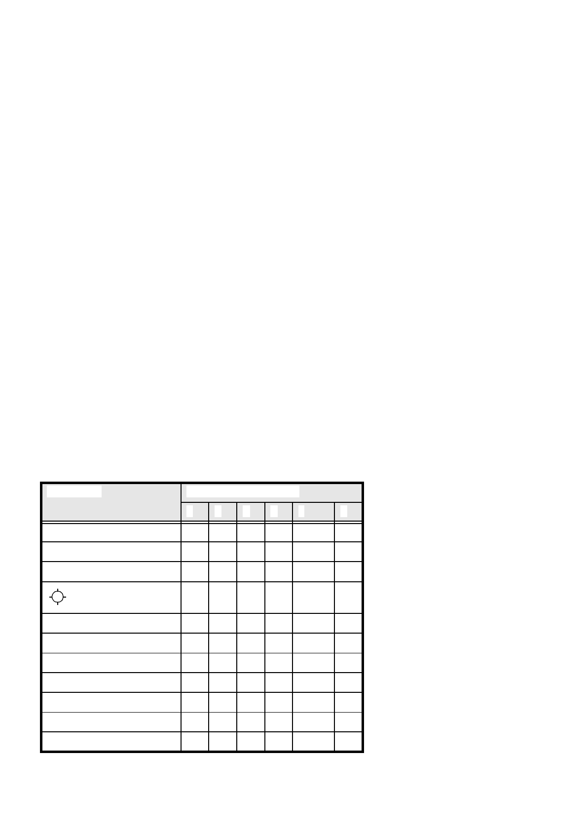
7.6.5.3 Recommendations concerning the Optimum Sequence of Methods
In the following table recommendations are provided for the optimum sequence of methods for components:
These are the abbreviations used:
B = ball driven
C = corner driven
G = grid driven
L = lead driven
R = row driven
S = size driven
* (L) applies to irregularly shaped components with separate windows
Component Measurement Sequence
S R G C L B
MELF S C L
CHIP S C L
SOT S C L
S L
SOJC6 S C
SOJC14 R C
LCC R C (L)
PLCC R C (L)
QFP R C (L)
TAB R C (L) *)
BGA, Flip chip G B
SIPLACE 80S/F/G User’s Manual 7 Vision Systems
Edition 07/97 from Software Version SR.010.xx 7.7 Guidelines for Describing Package Forms
Line engineer 7 - 97
7.7 Guidelines for Describing Package Forms
7.7.1 Transfer of Package Form Data and the Package Form Interpreter
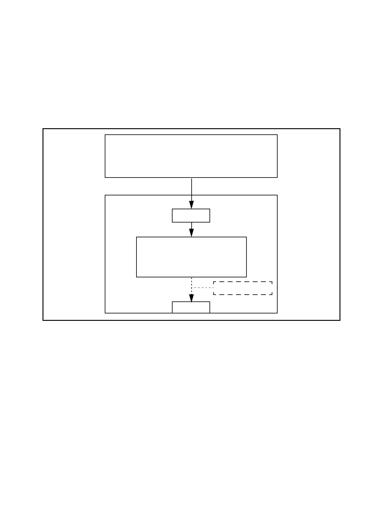
If a package form is transferred to the station without an .SST file, the package form interpreter will make cer-
tain settings to enable the package form to be measured in accordance with the package form description.
Fig. 7.7.1 Transfer of package form data without package form manipulation
In SIPLACE 80 S-15/F3 automatic placement machines, the package form interpreter is located in the machine
controller. The communication module transfers the signals for controlling the lighting from the MC to the cameras.
Tasks of the Package Form Interpreter
–
Automatic selection of suitable measuring modes
–
Automatic selection of the measuring parameters
–
Automatic differentiation between cubic/not cubic
–
Automatic setting of the lighting
The package form interpreter processes standard components and automatically identifies special compo-
nents. Under certain circumstances, other components have to be post-processed. If the package form set-
tings have to be manipulated, these changes will be stored in the .SST file and transferred back to the line
computer.
GF manipulator
LC
●
Package form library
●
Describe package form & components
●
Assign nozzles
●
Select cameras
Hard disk
.OGF
Package form interpreter
●
Automatic selection of meas. modes
●
Automatic lighting selection
SC
MVS
7 Vision Systems SIPLACE 80S/F/G User’s Manual
7.7 Guidelines for Describing Package Forms Edition 07/97 from Software Version SR.010.xx
7 - 98 Line engineer
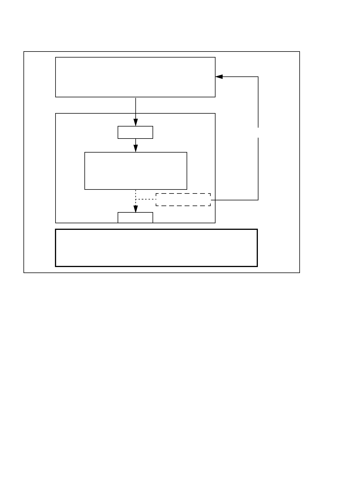
Fig. 7.7.2 Transfer of package form data with package form manipulation
If a package form is transferred to the station with the .SST file, then the settings for the .SST file for measur-
ing the package form will also be transferred. The package form interpreter will remain inactive.
7.7.2 Flow Charts for Programming and Testing a Package Form (GF)
Components are optically centered in SIPLACE automatic placement systems. It is also necessary to create
the package form description for the component on the SIPLACE line computer first. We recommend that you
always take the package form definitions and dimensions from the data sheet.
The package form settings can be modified at the station. There are different measuring methods. This
means that the lighting settings will also vary. Almost all components can be optically centered by combining
all the setting options in the optimum manner.
You should note, however, that a great many package forms have already been defined as standard. This
means that the manipulation of package forms at the station should be the exception, rather than the rule.
We can also provide the package form definitions of special components and hard to center components as
an extra service. Contact us for further details of this application.
GF manipulator
LC
Hard disk
.OGF
Package form interpreter
●
Automatic selection of meas. modes
●
Automatic lighting selection
SC
MVS
.SST
Important note:
Manipulation of components at the station must be the exception and not the rule.
In general, only a few components have to be changed.
●
Package form library
●
Describe package form & components
●
Assign nozzles
●
Select cameras