00191025-01.pdf - 第302页
7 Vision Systems S IPLACE 80S/F/G User’s Manual 7.7 Guidelines for D escribing Package Form s Edition 07/97 from Software Vers ion SR.010.xx 7 - 110 Line engine er Steep illumination level The mai n applicati on for the …

SIPLACE 80S/F/G User’s Manual 7 Vision Systems
Edition 07/97 from Software Version SR.010.xx 7.7 Guidelines for Describing Package Forms
Line engineer 7 - 109
NOTE
With respect to 0402 and 0603 components, avoid the nozzle being displayed during imaging. If this seems
likely, remove the component from the nozzle and use the 'Illumination Option' to see whether the nozzle did
appear in the image.
7.7.6.6 General Information on Setting Illumination Values
–
As a rule it is better to overilluminate the component than to underilluminate it. A saturated image is prefer-
able to a low-contrast image.
–
Optimum illumination is attained when only the leads are imaged and the component body is not shown.
–
If you cannot clearly separate the image of the component body from the leads, we recommend to illumi-
nate body and leads equally and then to measure the outline.
7.7.7 Setting the Components Illumination at the IC Head Camera
7.7.7.1 General Information on Illumination Methods
The idea of illumination setting is to obtain an image of the leads of a component which is as high-contrast as
possible. At the same time it is also important to suppress representation of the body of the component.
These instructions are intended to help you find the best possible illumination parameters. This, however,
does not imply that you rigidly comply with the values specified in these instructions. The way you should pro-
ceed is first to follow these instructions and then to adjust the parameters yourself where necessary. It may
well be that you come across one or other component the leads of which are better illuminated using values
different to the ones suggested in these instructions.
The illumination system comprises two different illumination levels. The intensities can be programmed indi-
vidually. By using the individual illumination levels one at a time or in combination with one another you can
adapt the illumination to suit a wide range of components.
Flat illumination level
The flat illumination level is used for illuminating BGAs, J-lead components (PLCC), and components with
convex-type leads. It tends to emphasize body and lead edges and suppresses reflective component sur-
faces.
Middle illumination level
The middle illumination level can be used universally with a wide range of components. With bright component
bodies, ceramic components and BGAs it should, however, only be used at lower intensity levels.
7 Vision Systems SIPLACE 80S/F/G User’s Manual
7.7 Guidelines for Describing Package Forms Edition 07/97 from Software Version SR.010.xx
7 - 110 Line engineer
Steep illumination level
The main application for the steep illumination level is for reflective leads, ceramic components and bright
component bodies. It is less suitable for reflective component bodies and BGAs.
NOTE
For the best illumination of most components a combination of these two lighting levels is required.
Using one illumination level will only be successful in exceptional cases.
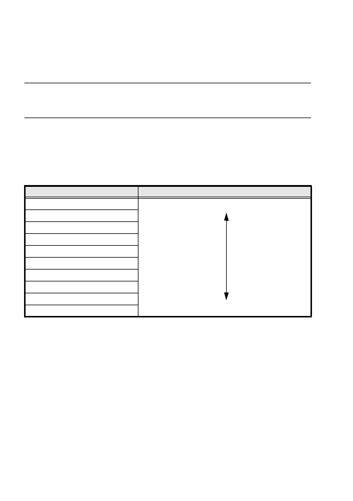
7.7.7.2 Pseudo-Color Display
The pseudo-color display is used to enable an informative and objective evaluation of the illumination to be
made. Each brightness value is represented by a different color.
IC head conversion table for the pseudo-color display
For measurement a contrast of at least 4 color steps is required between the leads and the body. Under the
GF manipulator's Illumination menu, components are displayed in pseudo-color on the station computer mon-
itor.
7.7.7.3 Settings for Illuminating Standard Components
The standard range of components includes tantalum capacitors, PLCCs, QFPs, SOs, SOJs, TSOPs, ICs,
power components, and BGAs.
For the components which are listed below the GF interpreter in the station computer uses the default illumi-
nation parameters listed in Fig. 7.7.9:
–
Tantalum capacitors (component bodies, non-reflective)
–
PLCC, QFP, SO, SOJ, TSOP, ICs
–
BGAs (not ceramic BGAs)
Color step Brightness
white light
yellow
orange
red
brown
green
light blue
blue
violet
black dark
SIPLACE 80S/F/G User’s Manual 7 Vision Systems
Edition 07/97 from Software Version SR.010.xx 7.7 Guidelines for Describing Package Forms
Line engineer 7 - 111
As a rule you will not need to change the illumination parameters for the standard components. For all other
components you will need to determine the illumination values and test them (see Section 7.7.7.4,
Page 7 - 111).
Fig. 7.7.9 Illumination parameters for standard components at the IC head camera
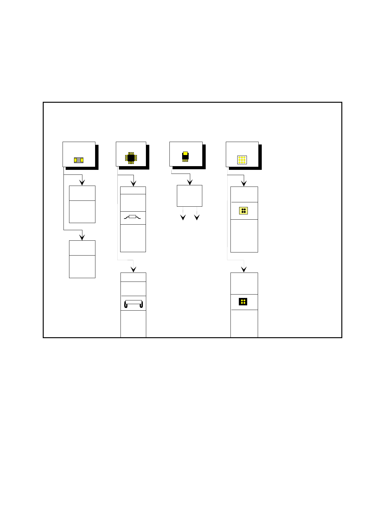
7.7.7.4 Settings for Illuminating Other Components
Fig. 7.7.10 presents a list of the illumination settings for other components.
Diagram for adjusting the illumination of standard components
IC
Power IC
BGA
Tantalum
capacitor
BGA
General
flat: 120
middle: 60
steep: 10
Reflective
body
Gullwing
SO, SOT,
TSOP
QFP,
flat: 90
middle: 40
steep: 10
flat: 255
middle: 90
steep: 0
flat: 120
middle: 50
steep: 10
J-Lead
PLCC
flat: 200
middle: 30
steep: 5
Ceramic
BGA
flat: 0
middle: 0-10
steep:80-100
flat: 255
middle: 30
steep: 0
Illumination
level
Brightness