00191025-01.pdf - 第308页
7 Vision Systems SIPLACE 80S /F/G User’s Manual 7.8 Teaching Fiducials: Additions to the 80F M achine Edition 07/97 from Software Version SR.010.xx 7 - 116 Line engine er
SIPLACE 80S/F/G User’s Manual 7 Vision Systems
Edition 07/97 from Software Version SR.010.xx 7.8 Teaching Fiducials: Additions to the 80F Machine
Line engineer 7 - 115
7.8 Teaching Fiducials: Additions to the 80F Machine
The placement machine 80F is, in contrast to the 80S machine, a single gantry machine. For this reason the
menu “Teach fiducials” does not include the option “Teach gantry” which you could use with the 80S machine
to select gantry 1 or 2 for teaching.
Both the revolver placement head and also the IC placement head are mounted on this gantry. The camera
system for PCB centering is fitted to the revolver placement head.
All menus are identical to those for the SI80S machine with the exception of this option.
The description of the menu and its options will be found in Chapter 7.5 Teaching the Fiducial.
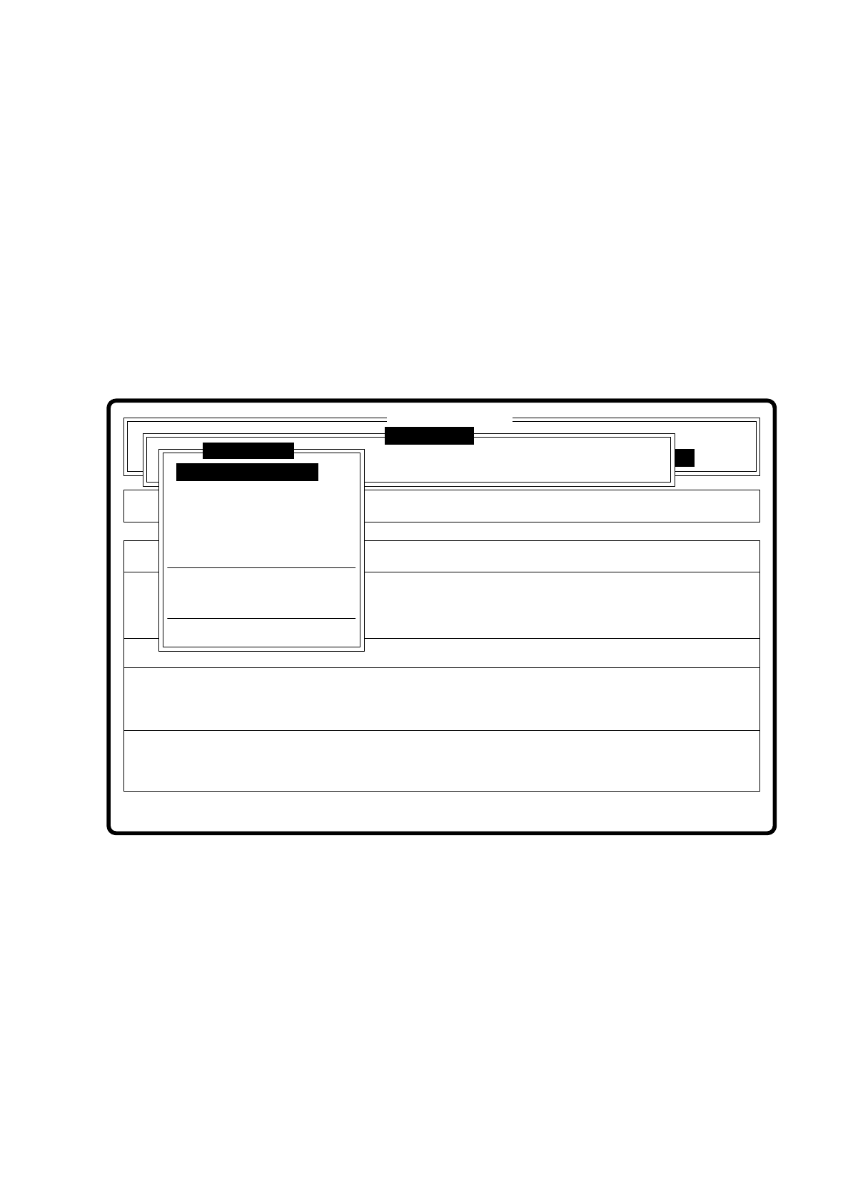
Fig. 7.8.1
Error
State
Action
Enter fiducial number to be processed
Single functions
:
:
:
SI80F V 10.x
Vision system
Vision system
Rüstung:
Cluster:
Vision system
Version: 2133
Enter fiducial number
New fiducial
Edit fiducial
Center fiducial
Test fiducial
Move x/y axes
PCB to center conveyor
PCB to output conveyor
Display errors
Teach fiducial

7 Vision Systems SIPLACE 80S/F/G User’s Manual
7.8 Teaching Fiducials: Additions to the 80F Machine Edition 07/97 from Software Version SR.010.xx
7 - 116 Line engineer

SIPLACE 80S/F/G User’s Manual 7 Vision Systems
Edition 07/97 from Software Version SR.010.xx 7.9 Test Component: Additions to the 80F Machine
Line engineer 7 - 117
7.9 Test Component: Additions to the 80F Machine
From version 6.x onwards multiple measurement is supported for optically centering fine-pitch components
with an edge length > 32 mm using the IC head. The maximum edge length of components amounts to 55 mm
for optical centering. Multiple measurement is triggered each time you call the options "Measure component"
or "Test component."
The following conditions apply to multiple measurement:
1. The number of measurements to be carried out is determined by the MVS system using a particular
algorithm. The component size and the tolerance values, for example, are entered into the algorithm.
2. In the MVS system the combination of various methods of measurements is specified. It is not possible
for you to alter the combination or hex parameters.
From version 7.x onwards it is also possible to optically center BGAs using the IC sensor.
From version 8.x onwards fine-pitch components and flip chips can be optically centered using the FC sensor.
For explanatory material and definitions concerning BGAs, flip-chips and the corresponding measuring meth-
ods, please refer to Section 7.6.3.4 Option “Measure component”.
Modification of the ball model description is explained in Section 7.6.4.3 Option "Ball Image". In the menu
Menu “Change measure mode” (see Section 7.6.5) you have the possibility of selecting various measurement
methods, of activating them and of modifying the associated hex parameter values.
Safety Information concerning the Components Vision Systems in the 80F Machine
DANGER
∆
!
∆
!
∆
!
You must not modify or tamper with the safety devices of the 80F machine or of the IC or flip chip module in
any way at all!
The optical radiation of the IC and flip chip sensors corresponds to laser class 1 provided the sensors are per-
manently installed in the machine (EN 60825-1 and IEC 825).
Fig. 7.9.1 Designation of laser class 1
Laser Class 1