00191025-01.pdf - 第312页
7 Vision Systems SIPLACE 80S /F/G User’s Manual 7.9 Test Component: Additions to the 80F Machine Edition 07/97 f rom Software Version SR.010.xx 7 - 120 Line engine er Key func tions ● With the s pace bar y ou can m ark t…
SIPLACE 80S/F/G User’s Manual 7 Vision Systems
Edition 07/97 from Software Version SR.010.xx 7.9 Test Component: Additions to the 80F Machine
Line engineer 7 - 119
7.9.2 Menu “Edit GF data”
7.9.2.1 Option “Adjust component type”
With the 80F machine the Menu “Edit GF data” (description see Section 7.6.4) was expanded by the addition
of the option “Adjust component type”.
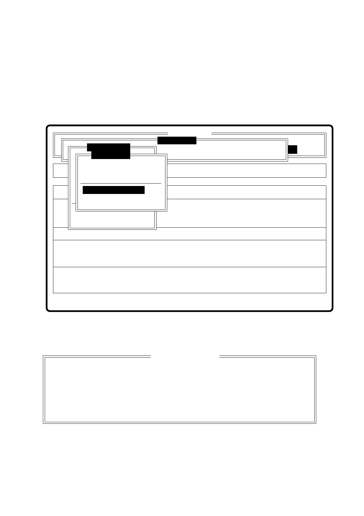
Fig. 7.9.3
When you select this option the following option box pops up.
Fig. 7.9.4
Select this option when centering errors occur with standard illumination. With these 4 selection possibilities
you can achieve optimal adjustment of the illumination to the component in question. Each of these options
contains specific combinations of the types of illumination: shallow, middle and steep angles.
Rüstung:
Single functions
Cluster:
SI80F V 10.x
Vision system
Vision system
Allestimento:
Version: 2133
BE abholen
BE darstellen
BE prüfen
GF-Daten ändern
Mess-Mode ändern
Nachfüllen
Display errors
BE messen
Test component
Edit GF data
Test output
Error
State
Action
:
:
:
Vision system
Select component type
Pin dimension
Package dimension
Ball image
Select component type
Illumination
Program transform
Esc: abort Ret: input Blank: select
Select component type
( ) Cubic, dull white
( ) Cubic, dull black
( ) Cubic, bright
( ) Cylindrical

7 Vision Systems SIPLACE 80S/F/G User’s Manual
7.9 Test Component: Additions to the 80F Machine Edition 07/97 from Software Version SR.010.xx
7 - 120 Line engineer
Key functions
●
With the space bar you can mark the corresponding component type
●
With “RETURN” finish making entries, and the option box is closed. You are returned to the menu “Edit GF
data”.
●
With “ESC” you may quit the option box, without accepting any change which may have been made.
7.9.2.2 Option “Illumination”
The option illumination has already been described for the revolver placement head in Section 7.6.4.4. You
have the possibility of choosing between two planes of illumination, shallow and steep.
For the component vision system of the IC head this option provides three planes of illumination:
–
shallow (bottom LED level)
–
middle (middle LED level)
–
steep (top LED level)
The keyboard commands are the same as those described in Section 7.6.4.4.
SIPLACE 80S/F/G User’s Manual 7 Vision Systems
Edition 07/97 from Software Version SR.010.xx 7.10 Coplanarity Laser Module (SIPLACE 80F only)
Line engineer 7 - 121
7.10 Coplanarity Laser Module (SIPLACE 80F only)
7.10.1 Functional Description
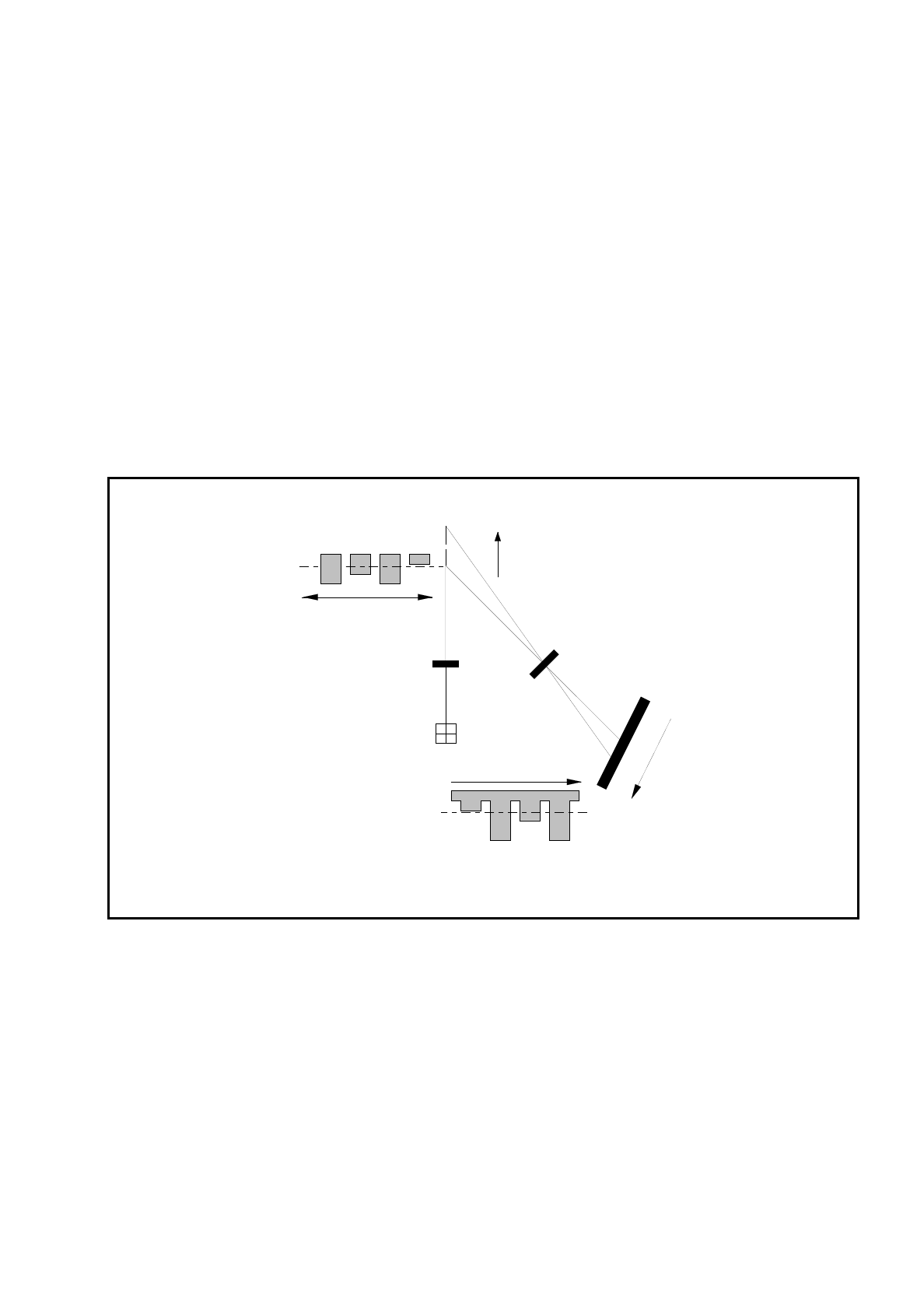
The coplanarity laser module is used to measure the vertical bends of the pins of components. The pin height
is measured with no physical contact on the principle of laser triangulation.
The placement head picks up the component which is to be tested, centers it optically using the IC camera,
and then traverses it with all four sides in succession over the stationary laser beam of the coplanarity laser
module. Every pin is scanned from below by the laser beam. The laser light scattered by the underside of the
pin is picked up by a sensor and serves as basis for the calculation of the exact position of the pin with respect
to the board. The positional values so determined are then compared with the limiting value prespecified by
the user. If this value is exceeded the component is discarded or returned.
Fig. 7.10.1 Measurement principle: laser triangulation
The coplanarity laser module is used in combination with optical component centering by means of the vision
system. Components with bent or missing pins are detected and if necessary discarded.
z = 0
+Z
+Z'
Z' = 0
Receiver lens
Detector
Measurement signal
Time t
Laser
Transmitter
Direction of travel