00191025-01.pdf - 第315页
SIPLACE 80S/F/G User’s Manual 7 Vision Systems Edition 07/97 from S oftware Version SR.010.xx 7.10 Coplanarity Laser Module (SIPLACE 80F only) Line engi neer 7 - 123 7.10.3 Safety Instructions DANGER ∆ ! ∆ ! ∆ ! The sa f…

7 Vision Systems SIPLACE 80S/F/G User’s Manual
7.10 Coplanarity Laser Module (SIPLACE 80F only) Edition 07/97 from Software Version SR.010.xx
7 - 122 Line engineer
7.10.2 Technical Data
Components: Can be used for “gull-wing” component forms
Component size and pin pitch restricted by the
component position recognition system,
i.e. max. size 43.0 mm x 43.0 mm x 11.0 mm.
Principle of measurement: Non-contact measurement by means of laser triangulation
Algorithm functions: JEDEC Standard - Calculation of the mounting level; all
deviations are determined with respect to this level. If a component
is lying aslant at the suction nozzle - which may, for example,
be caused by an adapter - this will therefore have no effect on
the "good/bad" decision.
Range of measurement: ± 0.75 mm (vertical)
Laser focus:
∅
25
µ
m
Laser power: 2.0 - 2.5 mW (maximum)
Wavelength: 750 nm
Resolution: 4
µ
m (vertical)
Repeatability: ± 10
µ
m (vertical)
Measuring precision: ± 20
µ
m (vertical)
Measurement time: approx. 2.5 - 4.5 sec/component for a QFP100 with 0.6 mm pitch
Control and communication: By means of a processor integrated into the module
V24 serial link to station computer
Module dimensions: approx. 440 mm x 30 mm x 85 mm
Place of installation: In machine base beside optic module
(mounted on a support)
Safety: When installed in the machine the coplanarity module complies
with Laser Class 1. The module will not function outside the machine
without additional wiring or interference with the safety functions.
If protective features are bypassed this automatically anticipates
a situation in conformity with
Laser Class 3B - Danger of Injury
to Skin and Eyes
- and therefore protective measures in accordance
with VBG 93 will be required.
SIPLACE 80S/F/G User’s Manual 7 Vision Systems
Edition 07/97 from Software Version SR.010.xx 7.10 Coplanarity Laser Module (SIPLACE 80F only)
Line engineer 7 - 123
7.10.3 Safety Instructions
DANGER
∆
!
∆
!
∆
!
The safety devices and the coplanarity laser module itself must not be modified or manipulated in any way
whatsoever!
The coplanarity laser module - without safety
features - corresponds to
Laser Class 3B.
(See also Fig. 7.10.4)
This means
danger to skin and eyes!
For this reason safety devices must not be
bypassed
under any circumstances!
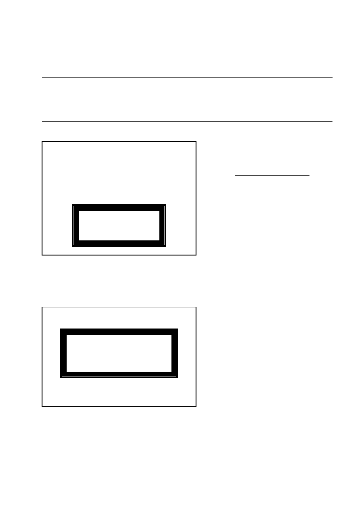
Fig. 7.10.2 Identification label for Laser Class 3B
The following safety devices have been fitted to the machine in order that the laser module can be operated
under
Laser Class 1
- No danger to skin or eyes:
The plug with the power supply (interlock line) is
permanently attached to the machine base. This
means that the laser module can only be oper-
ated within the machine.
The interlock line is connected in series to the
switches for the protective cover. Even if the key-
lock switch is operated to override protection,
this protection function is not disabled.
This means that the laser module can only be
operated
when the machine is closed!
Fig. 7.10.3 Identification label for Laser Class 1
K
Invisible laser radiation
Do not expose to beam
Laser class 3B
2.4mW max., 750nm; n.IEC 825-1(1993)
Laser Class 1
7 Vision Systems SIPLACE 80S/F/G User’s Manual
7.10 Coplanarity Laser Module (SIPLACE 80F only) Edition 07/97 from Software Version SR.010.xx
7 - 124 Line engineer
WARNING
∆
!
∆
!
∆
!
Modification or manipulation will cancel the manufacturer's safety warranty!
In addition the necessity will arise for the user of complying with the VGB 93 guidelines of the employers'
mutual indemnity association. This means:
- registration with the mutual indemnity association
- appointment of a laser safety officer
- drawing up of a code of practice for use of the module
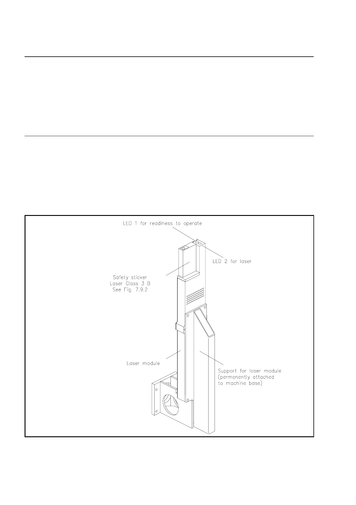
7.10.4 Overview
Two LEDs are fitted to the module for system monitoring. LED 1 is for monitoring operational readiness (
LED
on = ready to operate, LED off = not ready to operate
) and LED 2 monitors whether the laser is active or
inactive (
LED on = active, LED off = inactive
).
Fig. 7.10.4 General diagram of the coplanarity laser module