00191025-01.pdf - 第317页
SIPLACE 80S/F/G User’s Manual 7 Vision Systems Edition 07/97 from S oftware Version SR.010.xx 7.10 Coplanarity Laser Module (SIPLACE 80F on ly) Line engi neer 7 - 125 The fol lowing illu stration shows the positio n of t…
7 Vision Systems SIPLACE 80S/F/G User’s Manual
7.10 Coplanarity Laser Module (SIPLACE 80F only) Edition 07/97 from Software Version SR.010.xx
7 - 124 Line engineer
WARNING
∆
!
∆
!
∆
!
Modification or manipulation will cancel the manufacturer's safety warranty!
In addition the necessity will arise for the user of complying with the VGB 93 guidelines of the employers'
mutual indemnity association. This means:
- registration with the mutual indemnity association
- appointment of a laser safety officer
- drawing up of a code of practice for use of the module
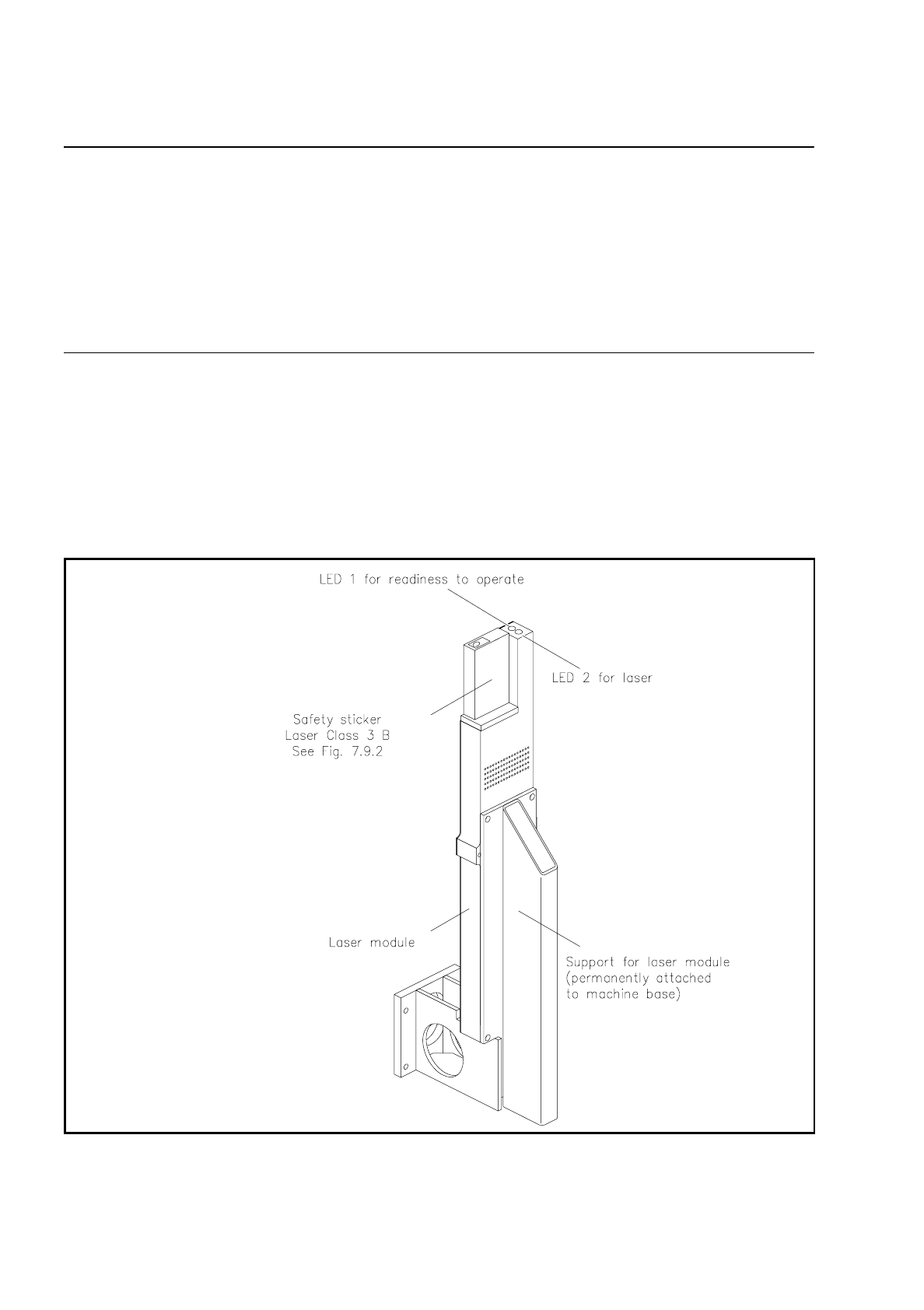
7.10.4 Overview
Two LEDs are fitted to the module for system monitoring. LED 1 is for monitoring operational readiness (
LED
on = ready to operate, LED off = not ready to operate
) and LED 2 monitors whether the laser is active or
inactive (
LED on = active, LED off = inactive
).
Fig. 7.10.4 General diagram of the coplanarity laser module
SIPLACE 80S/F/G User’s Manual 7 Vision Systems
Edition 07/97 from Software Version SR.010.xx 7.10 Coplanarity Laser Module (SIPLACE 80F only)
Line engineer 7 - 125
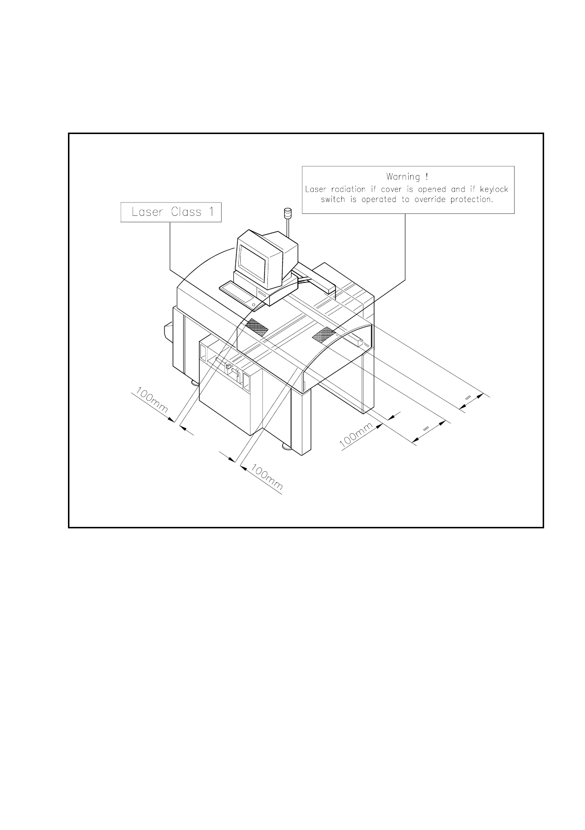
The following illustration shows the position of the safety instructions regarding operation of the coplanarity
laser module with the SIPLACE 80F. These instructions must be glued onto the cover at the locations indi-
cated by an arrow such that they are clearly visible (see Fig. 7.10.5).
Fig. 7.10.5 Safety instructions to be found on the SIPLACE 80F

7 Vision Systems SIPLACE 80S/F/G User’s Manual
7.10 Coplanarity Laser Module (SIPLACE 80F only) Edition 07/97 from Software Version SR.010.xx
7 - 126 Line engineer
7.10.5 Data Input
–
The coplanarity measurement must be entered in the package form editor under "Handling rules".
(see Section 5.4.4 "Package Form Editor" of the SIPLACE UNIX line computer operating manual).
–
Enter the maximum coplanarity deviation (see max. component height tolerance, Section 5.2.5 "Functions
of the Cluster Editor" of the SIPLACE UNIX line computer operating manual).
NOTE
With the "Placement options" menu (see Section 5.3 of this user's manual) you can deactivate or activate the
coplanarity laser module. Coplanarity measurement can be switched on or off for all of those components for
which coplanarity measurement has been set in the package form data.