00191025-01.pdf - 第333页
8 Component Supply S IPLACE 80S/F/G User’s Manual 8.1 Overview Edition 07/97 from S oftware Version SR.010.xx 8 - 8 8.1. 1.3 Technica l Data of B ulkcase Fee ders ) Bulkca se fee der Width Tracks per module Max. number o…

SIPLACE 80S/F/G User’s Manual 8 Component Supply
Edition 07/97 from Software Version SR.010.xx 8.1 Overview
8 - 7
8.1.1.2 Technical Data of Linear Vibratory Feeders
*)
This type of module can be used with SIPLACE 80S/F machines. However we recommend you to use
the module type 3 with SIPLACE 80S/F machines
Vibratory feeder Module
width
Tracks
per
module
Max. number
of modules
per station
Components
stock
Steel stick mag.
specific data
Width/ Qty.
Cycle
time
Power
supply
Linear vibratory feeder type 2
*)
from item no. 00142025-01
with adapter
from item no. 00116140-02
(replaced by
item no. 00142031-03)
30 mm 1,2,3 or 6 2 x 20
Max. 150 acc. to
components
length for each
stick magazine
4.5 mm / 6
9.5mm / 3
11 mm / 2
15 mm / 2
30 mm / 1
Depend-
ing on
comp.
24 VAC
50 Hz
Linear vibratory feeder type 3
from item no. 00142031-03
30 mm 1,2,3 or 6 2 x 20
Max. 150 acc. to
components
length for each
stick magazine
4.5 mm / 6
9.5mm / 3
11 mm / 2
15 mm / 2
30 mm / 1
Depend-
ing on
comp.
30 VDC
Tab. 8.1.2 Technical data for Vibratory feeders

8 Component Supply SIPLACE 80S/F/G User’s Manual
8.1 Overview Edition 07/97 from Software Version SR.010.xx
8 - 8
8.1.1.3 Technical Data of Bulkcase Feeders
)
Bulkcase feeder Width
Tracks
per
module
Max. number
of modules
per station
Comp.
stock
Feeder rails/ from item no.
Cycle
time
Power
supply
Base
from item no.
00142318-04
30 mm 2 2 x 20
approx.
5000
0603/045
0603/080
0805/045
0805/060
0805/085
0805/125
Mini-Melf
00142321-02
00142322-01
00142323-02
00142324-01
00142325-01
00142326-01
00142328-01
< 80 ms 30 VDC
Tab. 8.1.3 Technical data for bulkcase feeders
SIPLACE 80S/F/G User’s Manual 8 Component Supply
Edition 07/97 from Software Version SR.010.xx 8.2 Installation - General Information
8 - 9
8.2 Installation - General Information
8.2.1 Procedure for Installing Feed Modules
8.2.1.1 Preparatory Work
●
Select the setting range for the feed module which is to be used (see vibrator configuration).
●
When the placement head is in the waiting position press the emergency stop button.
●
Open the protective covers.
●
Make sure that the surface where the feed module is to be located (components table) is clean and that no
components can affect the firm seating of the feed module. Information on cleaning this surface (compo-
nents table) is to be found in the chapter on maintenance (Section 9.3.3 Component Tables).
8.2.1.2 Procedure
●
Set the conveyor to the track of the components table which has selected (see vibrator configuration).
●
Insert the module so that the rear side is fixed to the components table by the ball centering device, and
the front side by the corresponding centering pin. It is important here that the module is placed properly on
the components table with respect to its width.
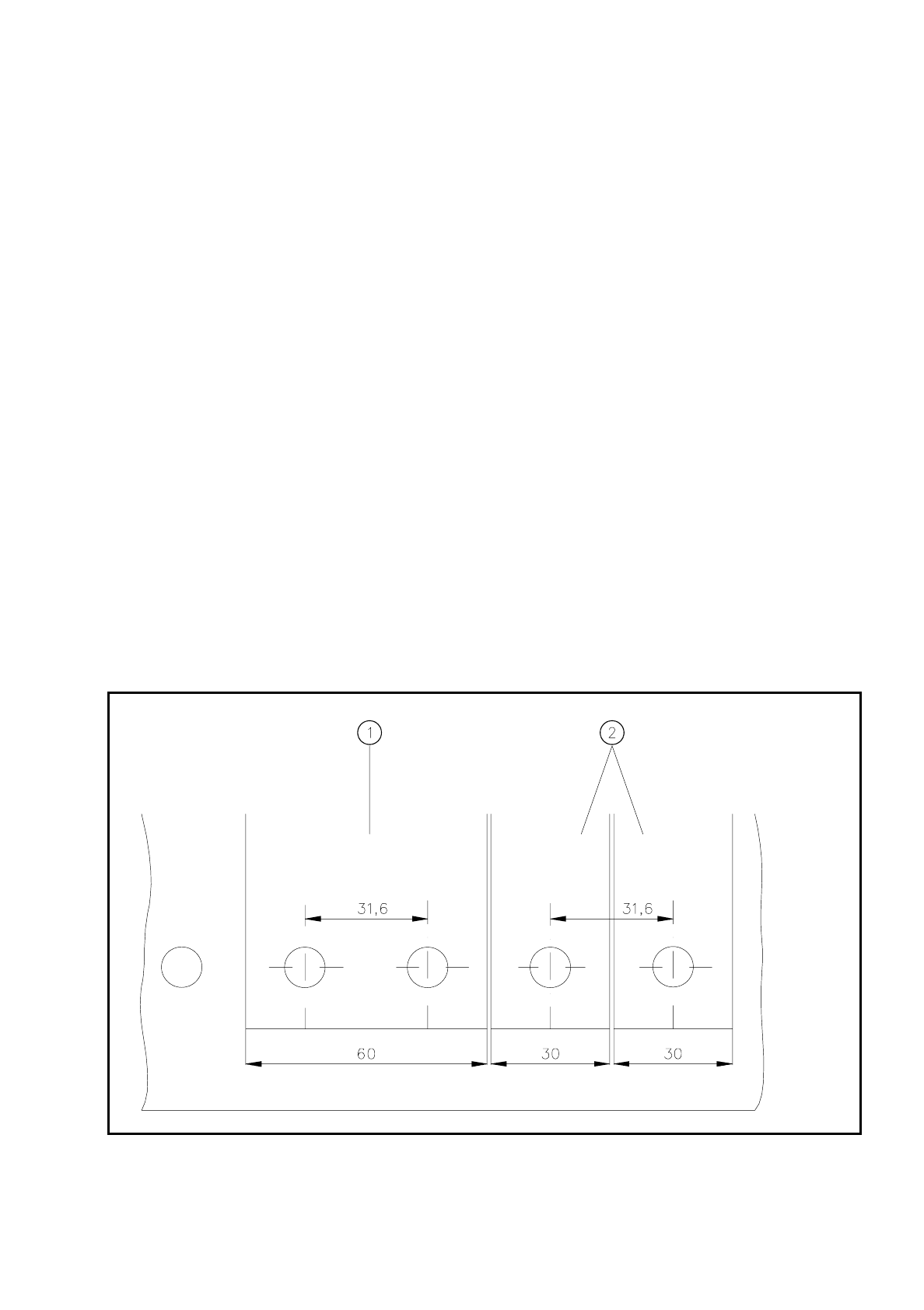
Fig. 8.2.1 Installation of modules with widths of 30 mm and 60 mm
- Key to Fig. 8.2.1
➀
Feeder module with width 60 mm
➁
Feeder module with width 30 mm