00191025-01.pdf - 第335页
8 Component Supply S IPLACE 80S/F/G User’s Manual 8.2 Installation - G eneral Information Edition 07/97 from Software Version SR.010.xx 8 - 10 Fig. 8.2.2 Installation of modules with width 45 mm - Key to F ig. 8.2. 2 ➀ F…
SIPLACE 80S/F/G User’s Manual 8 Component Supply
Edition 07/97 from Software Version SR.010.xx 8.2 Installation - General Information
8 - 9
8.2 Installation - General Information
8.2.1 Procedure for Installing Feed Modules
8.2.1.1 Preparatory Work
●
Select the setting range for the feed module which is to be used (see vibrator configuration).
●
When the placement head is in the waiting position press the emergency stop button.
●
Open the protective covers.
●
Make sure that the surface where the feed module is to be located (components table) is clean and that no
components can affect the firm seating of the feed module. Information on cleaning this surface (compo-
nents table) is to be found in the chapter on maintenance (Section 9.3.3 Component Tables).
8.2.1.2 Procedure
●
Set the conveyor to the track of the components table which has selected (see vibrator configuration).
●
Insert the module so that the rear side is fixed to the components table by the ball centering device, and
the front side by the corresponding centering pin. It is important here that the module is placed properly on
the components table with respect to its width.
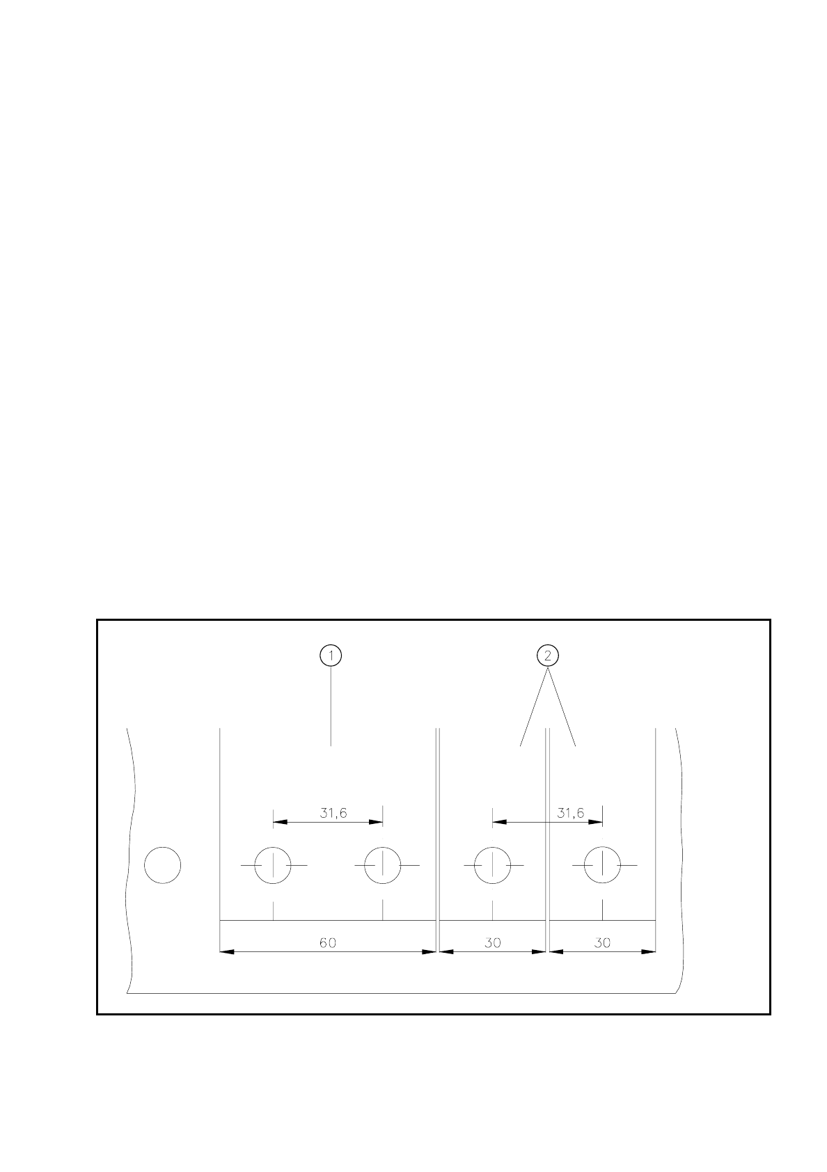
Fig. 8.2.1 Installation of modules with widths of 30 mm and 60 mm
- Key to Fig. 8.2.1
➀
Feeder module with width 60 mm
➁
Feeder module with width 30 mm
8 Component Supply SIPLACE 80S/F/G User’s Manual
8.2 Installation - General Information Edition 07/97 from Software Version SR.010.xx
8 - 10
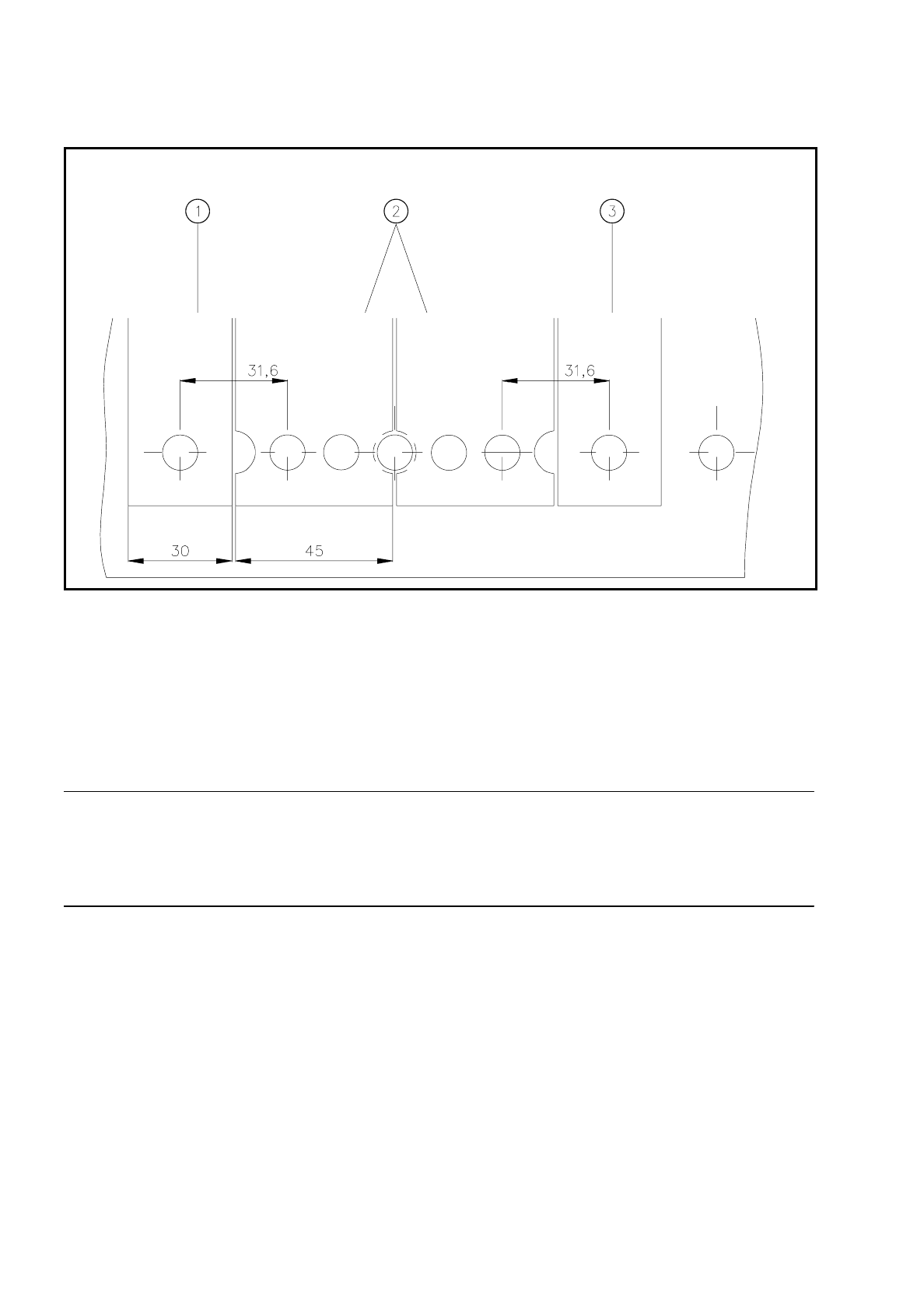
Fig. 8.2.2 Installation of modules with width 45 mm
- Key to Fig. 8.2.2
➀
Feeder module width 30 mm
➁
Feeder module width 45 mm
➂
Feeder module width 30 mm
●
Make sure that the module is seated securely on the components table.
●
Plug the module plug into the socket which is located under the parking location.
NOTE
Make sure that you do not fail to use the socket outlet which belongs to the parking location for plugging in the
module since control pulses for some modules are transmitted via this socket. If this is not observed, the con-
veyor may not work properly due to the wrong socket being used.
8.2.1.3 Final Activities
●
Close the covers and switch the control unit back on.
●
If applicable, perform a refill check (Section 5.3).
●
Proceed with placement.

SIPLACE 80S/F/G User’s Manual 8 Component Supply
Edition 07/97 from Software Version SR.010.xx 8.3 Changeable Components Tables
8 - 11
8.3 Changeable Components Tables
8.3.1 Function
The SIPLACE 80S/F placement machines are equipped with changeable components tables. These compo-
nents tables can be changed with relatively little effort.
8.3.2 Changing Component Tables
8.3.2.1 Removal
WARNING
OO
When you change the component table, always follow the sequence for removing the plugs from the commu-
nication unit and then connecting them again as described below. If you do not follow the specified order,
faults may occur in the component table.
8.3.2.2 Tools Required
WARNING
OO
Move the portal out of the range of the component table over the PCB transport. This will prevent the possibil-
ity of a head crash.
DANGER
OOO
Press the emergency stop button.
●
Remove the plugs from the power supply for the component table.
➁
.
●
Remove the communication plug
➀.
●
If necessary, remove the connector for the compressed air supply to the component table
➂.
●
Push the platform truck under the component table (A).
●
Loosen the two hexagon socket head screws for fixing the component table
➄.
From item number
Hexagon socket spanner, set
Component table platform truck 00123141-01