00191025-01.pdf - 第378页
SIPLACE 80S/F/G User’s Manual 9 Maintenance Edition 07/97 from S oftware Version SR.010.xx 9.3 Machine Base 9 - 19 Fig. 9. 3.1 Maintaining the width adj ustment device (PCB transport modules not shown) Key to Fig. 9.3.1 …

9 Maintenance SIPLACE 80S/F/G User’s Manual
9.3 Machine Base Edition 07/97 from Software Version SR.010.xx
9 - 18
9.3.2 PCB Handling
9.3.2.1 Cleaning the Conveyor Belts
NOTE
Components jammed in the conveyor area can easily cause the conveyor to jam or to boards being clamped
unevenly, which in turn can lead to an interruption of the placement sequence.
DANGER
∆
!
∆
!
∆
!
Switch the automatic placement system off at the main switch and disconnect from the power supply.
●
Switch the machine off at the main switch and open the safety hoods!
●
Check to see whether any components have got jammed in the area of the conveyor belts on either the
fixed or mobile sides of the conveyor, particularly between the clamping rail and the conveyor and also in
the area of the toothed-belt pulleys of the drive unit.
●
Clean off the conveyor belts with the vacuum cleaner and use tweezers to remove jammed components.
9.3.2.2 Maintenance of the Width Adjustment Device
DANGER
∆
!
∆
!
∆
!
Do not carry out any cleaning work with alcohol in the presence of naked lights or fire!
●
Preparatory work
●
Select:
PCB transport
→
Conveyor width
and make the corresponding choice to move the board
conveyor to its most open position.
DANGER
∆
!
∆
!
∆
!
Switch the automatic placement system off at the main switch and disconnect from the power supply.
●
Open the safety hoods.
●
Cleaning the recirculating ball screws and slide faces
●
Clean off the following faces (see Fig. 9.3.1) with the vacuum cleaner thoroughly:
–
the circumference of the recirculating ball screws,
–
the slide faces of the two flat guideways,
–
the bearing surfaces of the two guide rails and the entire area between the transport modules.
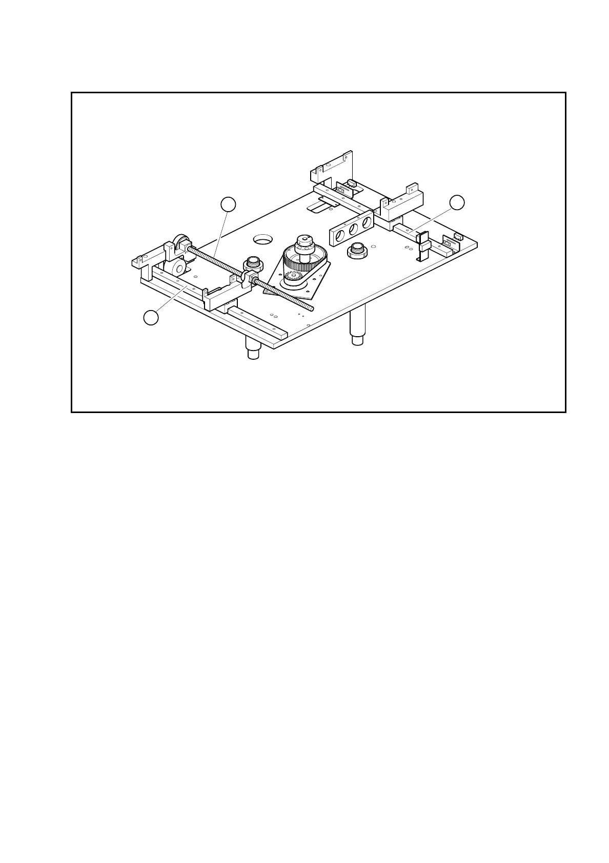
SIPLACE 80S/F/G User’s Manual 9 Maintenance
Edition 07/97 from Software Version SR.010.xx 9.3 Machine Base
9 - 19
Fig. 9.3.1 Maintaining the width adjustment device (PCB transport modules not shown)
Key to
Fig. 9.3.1
1 Spherical rotating liners for width adjustment
2 Flat guideways
●
Cleaning and oiling the recirculating ball screws of the width adjustment device
●
Clean thoroughly the recirculating ball screws of the width adjustment device by pulling a cloth soaked
in alcohol through each of the threads in turn.
●
If necessary use a brush soaked in alcohol. The bearings should not come into contact with alcohol.
●
After drying, apply a light and even film of watchmaker’s oil to the circumference of the spherical rotat-
ing liners.
●
Cleaning and greasing the flat guideways of the width adjustment
●
Rub the slide faces of the flat guideways with a lint-free cloth soaked in alcohol.
●
Grease these slide faces evenly and sparingly with Staburags N12. Remove excess grease.
1
2
2

9 Maintenance SIPLACE 80S/F/G User’s Manual
9.3 Machine Base Edition 07/97 from Software Version SR.010.xx
9 - 20
9.3.2.3 Cleaning the Dust Filter of the Control Unit
●
Control unit of ’PCB Handling’, right-hand side
●
Undo the four recessed head screws fastening the dust filter frame.
●
Clean the dust filter using a vacuum cleaner.
●
Control unit of ’PCB Handling’, left-hand side
●
Take off the dust filter frame fit to the control unit.
●
Clean the dust filter.
9.3.3 Component Tables
For all maintenance work on the components tables the feeder modules will have to be removed.
NOTE
The allocations of component, track number and module type are predefined for the placement of a batch of
components. If the components table is not being maintained in conjunction with a conveyor change or setting
up the machine, these allocations must be retained. If you do not have a data printout for the allocations of
track and feeder module (for example, ’Track X, 8 mm electric’) make a note of the allocations when you
remove the modules. You should also leave the tape rolls with the components in their respective roll compart-
ments so that you can refit them correctly later. To prevent the modules getting mixed up, we recommend you
first complete all of the maintenance work on one components table including refitting the modules before
starting on maintenance of the next components table.
9.3.3.1 Removing Feeder Modules
DANGER
∆
!
∆
!
∆
!
Switch the automatic placement system off at the main switch and disconnect from the power supply.
●
Open the safety hoods.
●
Slide the placement heads by hand far enough into the board conveyor area for them not to be damaged
when the feeder modules are removed from the components table. With the SIPLACE 80S-15 pay atten-
tion to the minimum clearance of the gantries (anti-crash switch), particularly before switching the machine
back on.
●
Remove the tapes with the components from the feeder modules:
Here you should cut the tape as far forward as possible and then pull the tape towards the end of the mod-
ule and out.
●
Immediately when you remove the module, write the track numbers on the module using a waterproof
marker pen. This will ease reinstallation later on.
●
Lift the feeder modules off the locating pins of the components table and set it down on a suitable, clean
surface outside the machine.