00191025-01.pdf - 第382页
SIPLACE 80S/F/G User’s Manual 9 Maintenance Edition 07/97 from S oftware Version SR.010.xx 9.3 Machine Base 9 - 23 Fig. 9. 3.2 Removing the components table 4 5 3 1 2 4 5 6 8 7 A

9 Maintenance SIPLACE 80S/F/G User’s Manual
9.3 Machine Base Edition 07/97 from Software Version SR.010.xx
9 - 22
9.3.3.6 Refitting the Feeder Modules
●
Remove the cover strips over the compressed air distributor block.
●
Replace the feeder modules back into the correct track on the components table.
●
Replace the tapes in the module (see Section 8 Component Supply of this user’s manual).
NOTE
If you are not certain of the assignment of the rolls to the division, have the location’s set-up displayed in
this way : Component feeding menu
→
Location no
→
Display set-up. Further information in this con-
nection will be found in Section 8 Component Supply of this user’s manual.
●
Close the safety hoods.
●
In the Single functions menu select the option Width adjustment and set the conveyor back to the width
of the board to be processed.
9.3.3.7 Removing and Installing the Component Table
●
Move the portal to the opposite side of the table.
DANGER
∆
!
∆
!
∆
!
Switch off the automatic placement system and disconnect from the power supply.
PLEASE NOTE
∆
!
∆
!
∆
!
Disconnect the automatic placement system from the compressed air supply.
●
Disconnect the mains plug for the component table
➁
.
●
Remove the communication plug
➀
.
●
If necessary, disconnect the compressed air supply from the component table
➂
.
●
Push the platform truck under the component table (A).
●
Loosen the two hexagon socket head screws for fixing the component table
➄
.
●
Open the horizontal tensioner
➆
.
●
Carefully raise the component table with the platform truck until the centering pins are
«
outside the holes.
●
Then pull out the component table.
●
Dismantle the cutter from the used tape chute.
●
Reverse the above sequence to reassemble.
SIPLACE 80S/F/G User’s Manual 9 Maintenance
Edition 07/97 from Software Version SR.010.xx 9.3 Machine Base
9 - 23
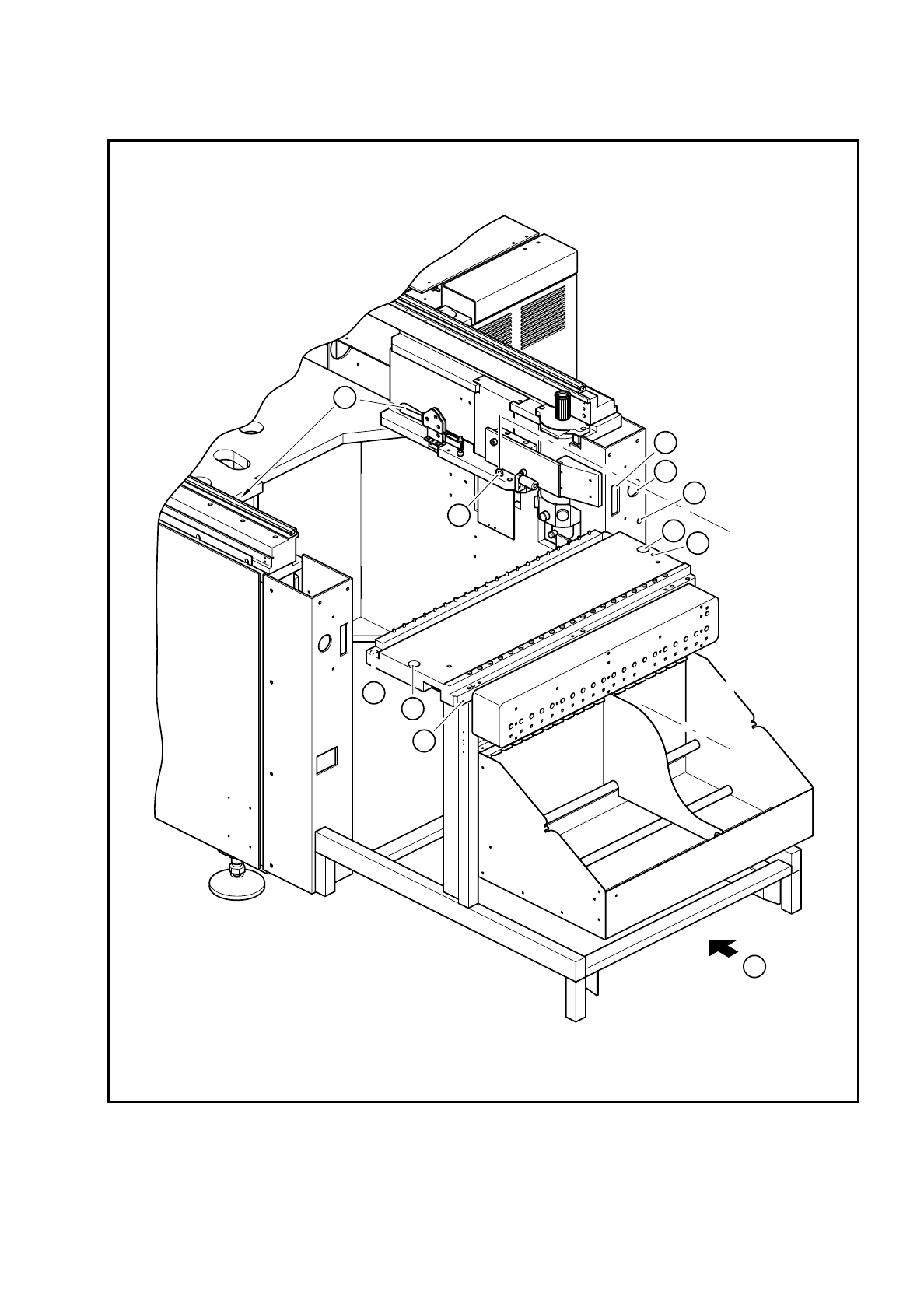
Fig. 9.3.2 Removing the components table
4
5
3
1
2
4
5
6
8
7
A

9 Maintenance SIPLACE 80S/F/G User’s Manual
9.3 Machine Base Edition 07/97 from Software Version SR.010.xx
9 - 24
Key to Fig. 9.3.2
9.3.4 Empty Tape Cutters of the SIPLACE 80S and 80F
NOTE
The empty tape cutters are located on both sides of the PCB transport in the machine base in front of the
changeable components tables (Fig. 9.1.1, Page 9 - 3).
9.3.4.1 Emptying the Waste Tape Container
Empty the waste tape container and remove all of the tape pieces in the bottom of the container with the vac-
uum cleaner.
9.3.4.2 Maintenance of the Guide Rail and Rotary Cutter Carriage, Checking the
Cutting Edge
DANGER
∆
!
∆
!
∆
!
Do not carry out any cleaning work with alcohol in the presence of naked lights or fire!
Do not remove the empty tape cutter for this maintenance work as otherwise setting will be necessary when it
is reinstalled. In addition, we recommend you to carry out maintenance of the cutter immediately after mainte-
nance of the components table, since you will not need to remove the feeder modules again from the compo-
nents table.
1 Connection for the communication interface
2 Connection for the power supply to the component table
3 Compressed air connection
4 Holes for the centering pins
5 Hexagon socket head screws for fixing the component table
6 Supporting surface for the component table
7 Horizontal tensioner
8 Centering pins
A Push in the component table lifting truck