00191025-01.pdf - 第401页
9 Maintenance SIPLACE 80S /F/G User’s Manual 9.4 Gantries Edition 07/97 from Software Version SR.010.xx 9 - 42
SIPLACE 80S/F/G User’s Manual 9 Maintenance
Edition 07/97 from Software Version SR.010.xx 9.4 Gantries
9 - 41
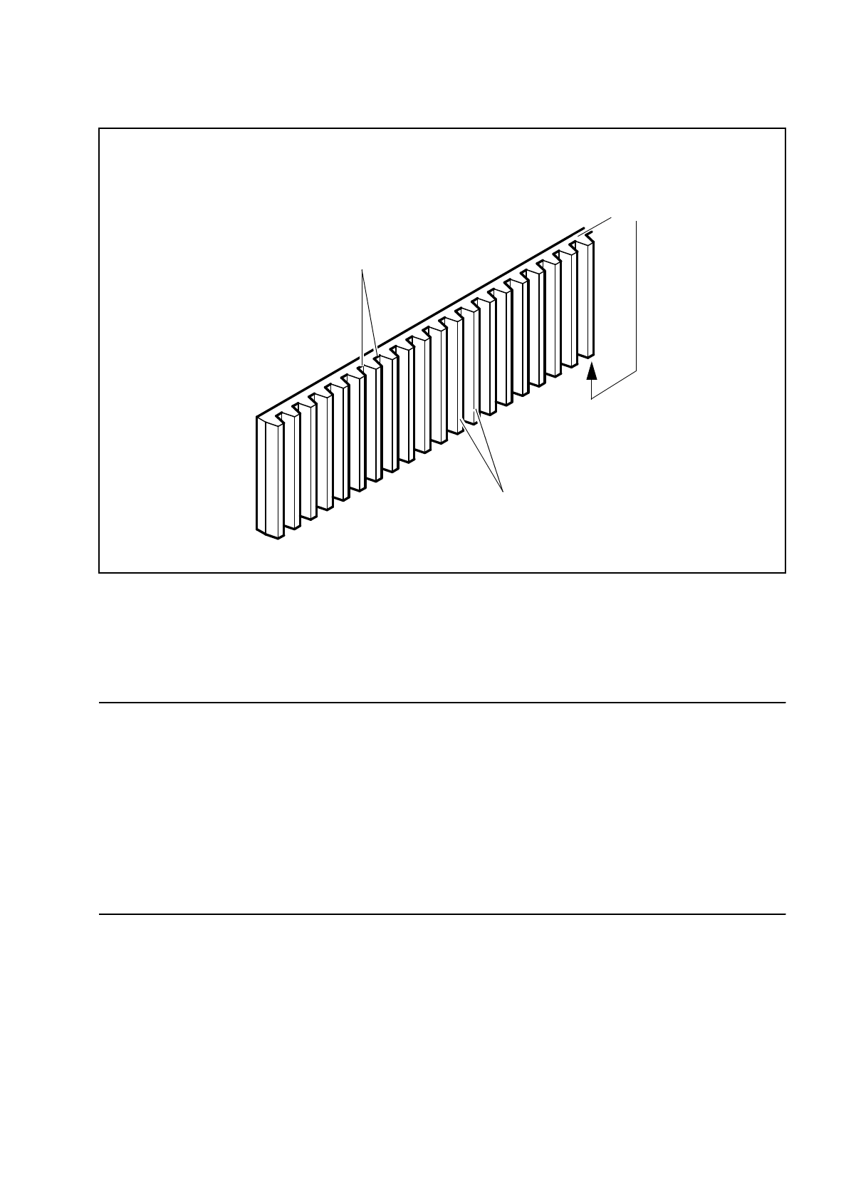
Fig. 9.4.3 Greasing the roots, the tips, and the upper and lower side faces of the toothed belt
9.4.3 X/Y Measurement System
NOTE
Contaminated scales result in counting errors with the x or y gantry axes and thus to incorrect or inaccurate
placement.
To prevent the x and y axis scales accidentally coming into contact with grease again after cleaning we recom-
mend that all scales only be cleaned once all other work has been completed which calls for greasing or oiling
parts.
The x and y incremental scales are glued on. For this reason moisten a cloth with alcohol and clean the scales
being careful to ensure that the glued surfaces do not come into contact with alcohol.
For the location of the measurement systems of the x and y axes please refer to Fig. 9.4.2.
9.4.3.1 Cleaning the incremental Scales of the X and Y Axes
Clean the incremental scales by wiping them over with a soft, clean and lint-free cloth and a little alcohol.
Move the axes so that you reach all parts of the incremental scales.
Root of the tooth
Tip of the tooth
Side faces of the
toothed belt

9 Maintenance SIPLACE 80S/F/G User’s Manual
9.4 Gantries Edition 07/97 from Software Version SR.010.xx
9 - 42

SIPLACE 80S/F/G User’s Manual 9 Maintenance
Edition 07/97 from Software Version SR.010.xx 9.5 Revolver Head, Segment Version 2 (New Nozzle Seat)
9 - 43
9.5 Revolver Head, Segment Version 2 (New Nozzle
Seat)
NOTE
During all work which you perform on the segment you must comply with the instructions provided in the Short
Reference Maintenance for segments, version II. order no. 00190442-01.
9.5.1 Inspecting and Cleaning the Jaws of the Centering Station
For this maintenance work the mechanical centering station remains installed in the revolver head, as do the
segments.
The location of the centering station at the revolver head is shown in Fig. 9.5.4.
●
Remove the light gate from the placement head, as described in the section "9.5.3 Removal and Reinstal-
lation of the Housing Complete with Star". This makes the centering station accessible for maintenance.
●
During the following work make sure that the glass disks of the segments are not touched and nothing
drops into the placement head.
●
Clean the two jaw pairs with a Q-tip moistened with alcohol and without applying pressure to the jaws.
NOTE:
With obstinate dirt or if there are metallic depositions the jaws will have to be replaced. This is described in
the maintenance manual for the G3 centering station. In addition and among other things it will be neces-
sary to remove the centering station from the placement head and adjust the new jaws with the adjust-
ment device. This work must only be carried out by specially trained personnel!
●
Continue work with CRL compensation, as described below.
9.5.2 Identity Tester - CRDL
NOTE
Before carrying out C, R and L compensation the jaw pairs of the centering station must be maintained as
described above in order for there to be optimal electrical contact.
In the course of maintenance carry out C, R and L compensation for the identity testers CRDL 1 and 2.
This will yield you the actual initial values for the identity test in the placement sequence. The compensation
values obtained are automatically saved and therefore are retained after the machine is switched off.