00191025-01.pdf - 第402页
SIPLACE 80S/F/G User’s Manual 9 Maintenance Edition 07/97 from S oftware Version SR.010.xx 9.5 Revolver Head, S egment Version 2 (New N ozzle Seat) 9 - 43 9.5 Revolver Head, Segment Version 2 (New Nozzle Seat) NOTE Durin…

9 Maintenance SIPLACE 80S/F/G User’s Manual
9.4 Gantries Edition 07/97 from Software Version SR.010.xx
9 - 42

SIPLACE 80S/F/G User’s Manual 9 Maintenance
Edition 07/97 from Software Version SR.010.xx 9.5 Revolver Head, Segment Version 2 (New Nozzle Seat)
9 - 43
9.5 Revolver Head, Segment Version 2 (New Nozzle
Seat)
NOTE
During all work which you perform on the segment you must comply with the instructions provided in the Short
Reference Maintenance for segments, version II. order no. 00190442-01.
9.5.1 Inspecting and Cleaning the Jaws of the Centering Station
For this maintenance work the mechanical centering station remains installed in the revolver head, as do the
segments.
The location of the centering station at the revolver head is shown in Fig. 9.5.4.
●
Remove the light gate from the placement head, as described in the section "9.5.3 Removal and Reinstal-
lation of the Housing Complete with Star". This makes the centering station accessible for maintenance.
●
During the following work make sure that the glass disks of the segments are not touched and nothing
drops into the placement head.
●
Clean the two jaw pairs with a Q-tip moistened with alcohol and without applying pressure to the jaws.
NOTE:
With obstinate dirt or if there are metallic depositions the jaws will have to be replaced. This is described in
the maintenance manual for the G3 centering station. In addition and among other things it will be neces-
sary to remove the centering station from the placement head and adjust the new jaws with the adjust-
ment device. This work must only be carried out by specially trained personnel!
●
Continue work with CRL compensation, as described below.
9.5.2 Identity Tester - CRDL
NOTE
Before carrying out C, R and L compensation the jaw pairs of the centering station must be maintained as
described above in order for there to be optimal electrical contact.
In the course of maintenance carry out C, R and L compensation for the identity testers CRDL 1 and 2.
This will yield you the actual initial values for the identity test in the placement sequence. The compensation
values obtained are automatically saved and therefore are retained after the machine is switched off.
9 Maintenance SIPLACE 80S/F/G User’s Manual
9.5 Revolver Head, Segment Version 2 (New Nozzle Seat) Edition 07/97 from Software Version SR.010.xx
9 - 44
●
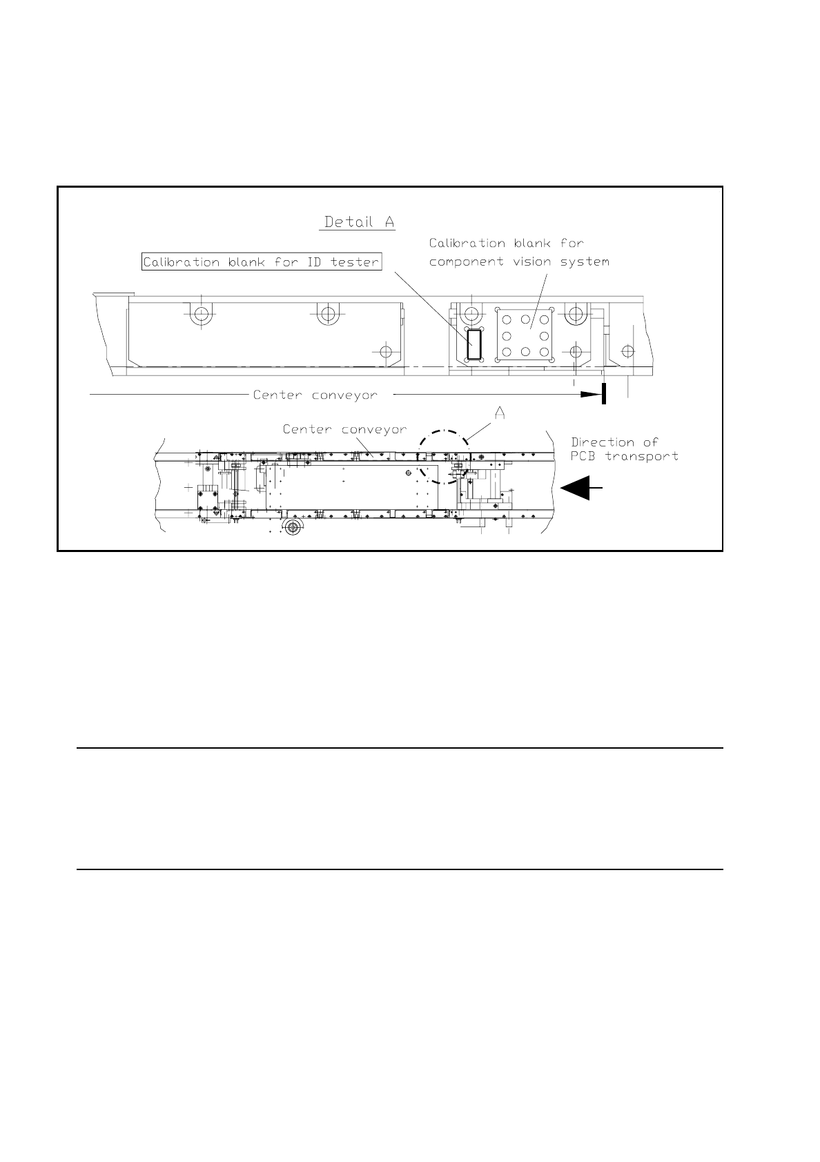
Before carrying on with your work check to see whether the "Calibration unit RLCD is in the pocket on the
right-hand front part of the fixed side of the center PCB conveyor (see Fig. 9.5.1). The calibration unit must
be greasefree to ensure optimum electrical contact.
Fig. 9.5.1 Provision of the calibration unit for identity testing on the fixed side of the PCB conveyor
9.5.2.1 Sequence of Operations
●
From the main menu select with the aid of the cursor + return: Single functions
→
Gantry 1
●
Then select "Star head"
→
"Tester".
●
Open the protective cover and with the aid of tweezers insert the calibration unit (which has been cleaned
with alcohol) into the pocket on the PCB conveyor (see Fig. 9.5.1).
NOTE
The calibration unit for the identity tester will not be required for the following C compensation, in other
words, not inserted!
But in principle C compensation can also be carried out with a calibration unit inserted as the jaws remain
open during C compensation.