00191025-01.pdf - 第410页
SIPLACE 80S/F/G User’s Manual 9 Maintenance Edition 07/97 from S oftware Version SR.010.xx 9.5 Revolver Head, S egment Version 2 (New N ozzle Seat) 9 - 51 9.5. 4.1 Cleaning and Greasing the Tooth Engagement of the Swivel…

9 Maintenance SIPLACE 80S/F/G User’s Manual
9.5 Revolver Head, Segment Version 2 (New Nozzle Seat) Edition 07/97 from Software Version SR.010.xx
9 - 50
9.5.3.3 Concluding work
For this work you will require the SIPLACE test program !
DANGER
∆
!
∆
!
∆
!
The test program may only be used by authorized persons trained at Siemens AG.
The machine setter password is necessary for the executive functions.
If the test program is used incorrectly or improperly there is an increased danger of accident and also the dan-
ger of damage to the machine.
The key-operated switch will remain locked (= not actuated) for all work described below, and the protective
covers will remain closed.
Proceed in the sequence of operations given.
●
Close the protective covers and lock the key-operated switch. Lock away in turn the key! Switch the
machine on.
●
Load the SIPLACE test program from the diskette.
●
First carry out the star reference run and without segments so as to position the star position 1 at star sta-
tion 1 (= below). Afterwards you can return the segments to their allocations in the star. Proceed as follows:
Check whether the z axis is in the top end position. If it is not first select: menu "Axes"
→
z axis
→
Refer-
ence point. After this select from the "axes" menu
→
Star axis
→
Reference point.
●
Continue work with installation of the segments, as described in the section of the same name.
●
First calibrate the PCB vision system and next the component vision system.
NOTE
In the course of this work first the head and next the gantry reference run is carried out.
●
Check or determine the machine zero point.
●
Load the station software and start the placement sequence.
9.5.4 Turning stations dp1 and dp2
NOTE
for this maintenance work the "housing complete with star" is removed and placed on the "mounting rack for
housing", as described in the section 9.5.3.1 Removal of the Housing Complete with Star.
The turning stations remain installed on the housing for the duration of maintenance as otherwise you will
need to reset the track signals after reinstallation!
The location of the turning stations on the "housing complete with star" is shown in Fig. 9.5.4.
SIPLACE 80S/F/G User’s Manual 9 Maintenance
Edition 07/97 from Software Version SR.010.xx 9.5 Revolver Head, Segment Version 2 (New Nozzle Seat)
9 - 51
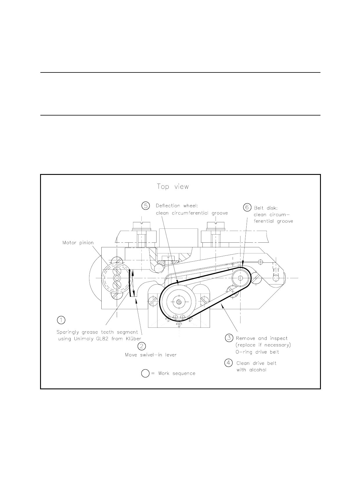
9.5.4.1 Cleaning and Greasing the Tooth Engagement of the Swivel-In Lever
NOTE
If the tooth engagement on the swivel-in lever is not greased this can lead to stiffness when the lever swivels
in or out of position and this in turn to fatal error message Nos. 1 or 2 with placement being stopped immedi-
ately.
●
Clean the teeth of both the pinion and also the tooth segment on the swivel-in lever with a brush dipped in
alcohol (see Fig. 9.5.5). While doing so move the swivel-in lever by hand.
●
Carefully dry off the teeth if necessary with compressed air and grease the tooth segment sparingly with
Unimoly GL82.
●
Swivel the lever repeatedly in and out in order to distribute the grease evenly.
Fig. 9.5.5 Maintenance of turning stations 1 and 2

9 Maintenance SIPLACE 80S/F/G User’s Manual
9.5 Revolver Head, Segment Version 2 (New Nozzle Seat) Edition 07/97 from Software Version SR.010.xx
9 - 52
9.5.4.2 Cleaning and Replacing the Drive Belt
NOTE
If the O-ring drive belt of the turning station is not absolutely greasefree, transmission of the rotary movement
to the segment (driving disk) will not be optimal. This will result in turn in various error messages, such as for
example Nos. 3, 4, and 5.
Clean the O-ring drive belts only after maintenance of the swivel-in levers.
Spare part
O-ring (drive belt), 19 x 1.5 E70 B243E, Item No. 00327165S01
●
Check beforehand the O-ring drive belt (see Fig. 9.5.5). If the belt is damaged or too slack replace the O-
ring.
●
Lift the drive belt out of the circumferential groove of the deflection wheel and of the pulley.
●
Clean the drive belts with a clean, lintfree cloth soaked in alcohol.
NOTE
While doing so do not overstretch the drive belt!
Do not use solvent, only alcohol!
●
Clean in addition the circumferential groove of the deflection wheel and the pulley with alcohol.
●
Insert the dry drive belt (or, if applicable, a greasefree replacement O-ring drive belt) into the dry circumfer-
ential groove of the deflection wheel. Attention: Do not now allow any further contact with grease!
●
Now lift the drive belt into the circumferential groove of the pulley without overstretching the drive belts!
9.5.5 Star
9.5.5.1 Servicing the Longitudinal Guide Columns and Rails,
Cleaning the Vacuum Connection Tubes
NOTE
The "housing complete with star" is removed for this maintenance work and placed on the "mounting rack for
housing", as described in the section 9.5.3.1 Removal of the Housing Complete with Star.
The complete star assembly remains mounted to the housing for the duration of maintenance work!
The location of the star is shown in Fig. 9.5.4.
●
Clean the guide columns, the vacuum connection tubes and the longitudinal guide rails of the star with a
pipe cleaner soaked in maintenance fluid of the segment maintenance cloth (see Short Reference Mainte-
nance Segments Version 2).
●
Clean all guideway shafts and rails and the vacuum connection tubes by wiping them over with the seg-
ment maintenance cloth. Then move the longitudinal guide cages repeatedly along the rails.