00191025-01.pdf - 第418页
SIPLACE 80S/F/G User’s Manual 9 Maintenance Edition 07/97 from S oftware Version SR.010.xx 9.5 Revolver Head, Segment Version 2 (New Nozzle Seat) 9 - 59 9.5.9.2 I nspecting, Cleani ng and Greasing the O-Rings ● Check th …
9 Maintenance SIPLACE 80S/F/G User’s Manual
9.5 Revolver Head, Segment Version 2 (New Nozzle Seat) Edition 07/97 from Software Version SR.010.xx
9 - 58
●
If clogging is slight proceed as follows:
●
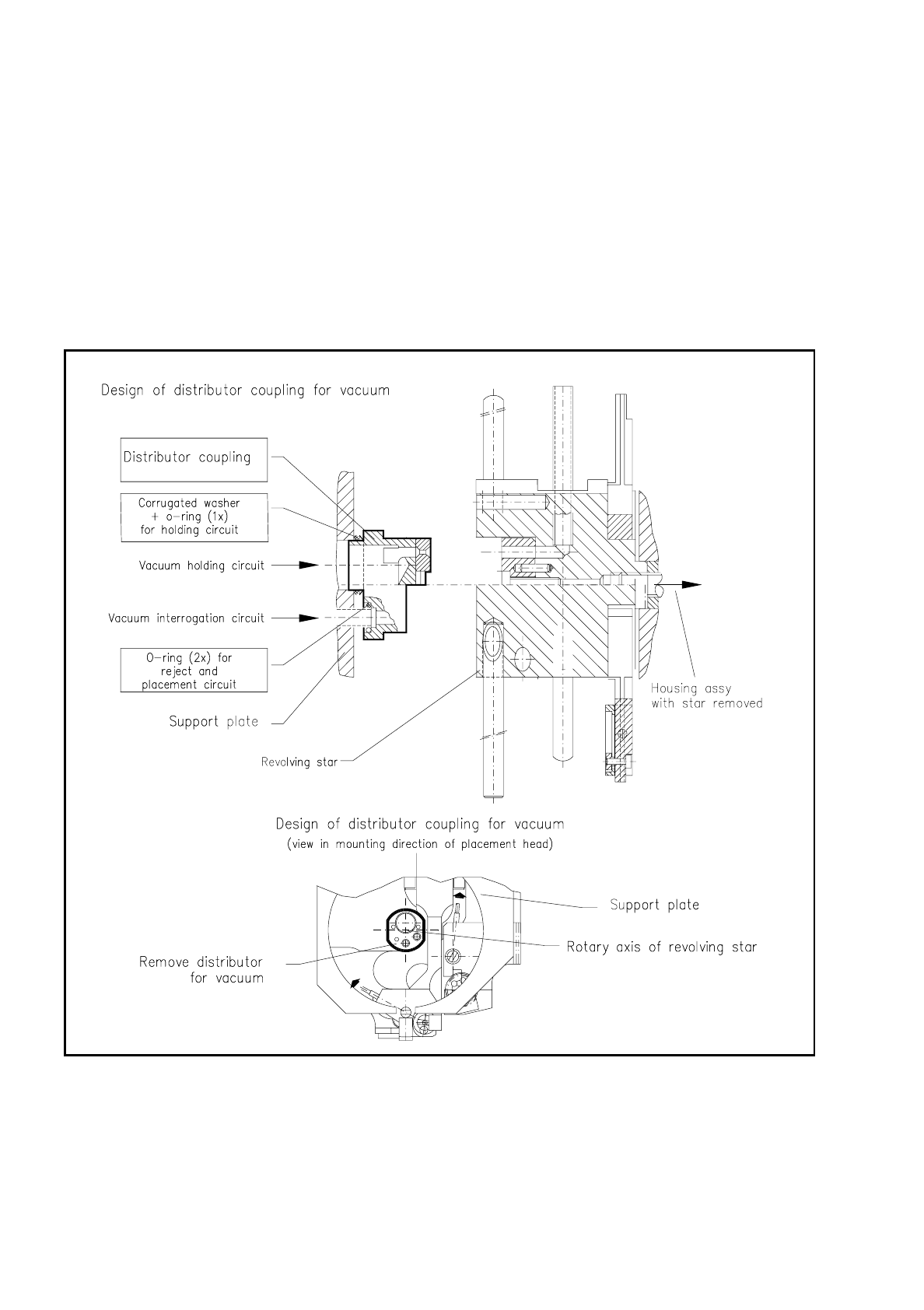
Remove the O-rings from the vacuum distributor coupling, which has been removed, and the bore in
the support plate (see Fig. 9.5.11).
●
With alcohol (no solvent!) clean the visible surfaces of the coupling, and in particular also the bores for
the O-rings and also the external circumference of the connection tube of the holding circuit.
●
Clean the bore in the support plate and the circumference of the two small connection tubes.
●
With clean compressed air blow out thoroughly the individual holes - only the holes of the distributor
coupling, not of the support plate ! - and the outer surface of the distributor coupling. All surfaces of
and holes in the coupling and the support plate must then be dry!
Fig. 9.5.10 Location of the vacuum distributor coupling on the support plate, and removal of the distributor coupling
SIPLACE 80S/F/G User’s Manual 9 Maintenance
Edition 07/97 from Software Version SR.010.xx 9.5 Revolver Head, Segment Version 2 (New Nozzle Seat)
9 - 59
9.5.9.2 Inspecting, Cleaning and Greasing the O-Rings
●
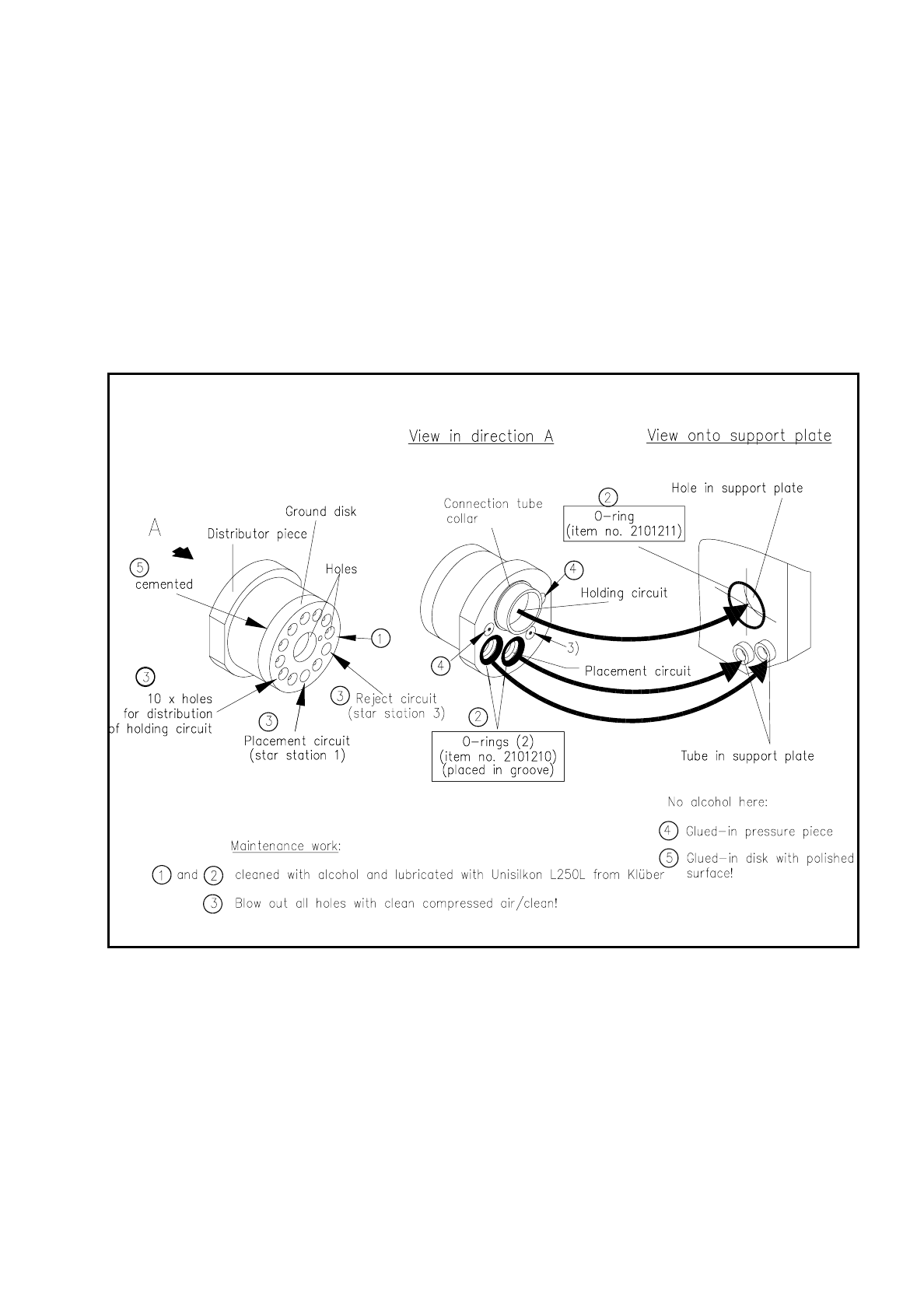
Check the two small O-rings of the vacuum distributor coupling and the larger O-ring of the support plate
(see Fig. 9.5.11). Replace damaged O-rings (for Item Nos. see Fig. 9.5.11).
●
Clean the 3 O-rings with alcohol, and then grease them sparingly with UNISILKON L250L.
Grease the new O-rings too!
●
Insert the small O-rings into the vacuum distributor coupling bores and the larger O-ring into the support
plate bore, as shown in Fig. 9.5.11.
●
Insert the vacuum distributor coupling into the support plate, pushing against the resistance of the O-rings
so that the spring plungers (4) touch lightly against the support plate.
Fig. 9.5.11 Location of the vacuum distributor coupling on the support plate, and removal of the distributor coupling

9 Maintenance SIPLACE 80S/F/G User’s Manual
9.5 Revolver Head, Segment Version 2 (New Nozzle Seat) Edition 07/97 from Software Version SR.010.xx
9 - 60
9.5.10 Segments, Version 2
NOTE
In this section the maintenance of the segments with sealing piston version 2 (new nozzle seat and grease-
free maintenance) is described. The new "sleeve complete" (with O-ring!) and the new nozzle (with reference
web) are also always fitted to the segments with sealing piston version 2.
9.5.10.1 Removal of the Segments
●
With the 80 S and F machines select: Single functions
→
Gantry 1
→
Go to service pos'n
→
Start key
(green key). The revolver head is brought forwards into a good position for working.
●
Select next: Star head
→
Cycle star. The star position (= segment number) which is at star station 7 at the
top is displayed on the screen. Unlock the key-operated switch.
●
Open the sliding safety door above the placement head and also the flap of the light gate on the placement
head (see Fig. 9.5.2).
NOTE
The glass disk must not be damaged. If it is damaged a new "sleeve complete" must be fitted into the seg-
ment (see maintenance manual).
●
Carefully remove the segment in the top position with the correct segment removal tool , as shown in Fig.
9.5.12.
Note: This tool exists in 2 versions. For the segments with sealing piston version 2 you will need the tool
with the Item No. 00305897-02.
NOTE
If "Segment number X" is displayed on the screen, this always stands for "Star position number X". In the
ideal case the segment number (1-12) corresponds to the star position number (1-12), but after individual
segments have been replaced this may no longer be necessarily the case.
●
For this reason when you remove segments make a note straightaway of the allocation of the star position
number (= number on the screen) from which you removed the segment to the segment number
(= last number of the numerical sequence on the segment body, for example, "12").
NOTE
The star nozzle configuration "ACTUAL" must be reestablished after maintenance work during the place-
ment of a batch in order that the time-optimized placement sequence is once again assured.
Nozzles and segments should not be swapped around. Compliance with this will also make fault location
easier.