00191025-01.pdf - 第420页
SIPLACE 80S/F/G User’s Manual 9 Maintenance Edition 07/97 from S oftware Version SR.010.xx 9.5 Revolver Head, S egment Version 2 (New N ozzle Seat) 9 - 61 ● Place e ach segment immediat ely after remo val caref ully int …

9 Maintenance SIPLACE 80S/F/G User’s Manual
9.5 Revolver Head, Segment Version 2 (New Nozzle Seat) Edition 07/97 from Software Version SR.010.xx
9 - 60
9.5.10 Segments, Version 2
NOTE
In this section the maintenance of the segments with sealing piston version 2 (new nozzle seat and grease-
free maintenance) is described. The new "sleeve complete" (with O-ring!) and the new nozzle (with reference
web) are also always fitted to the segments with sealing piston version 2.
9.5.10.1 Removal of the Segments
●
With the 80 S and F machines select: Single functions
→
Gantry 1
→
Go to service pos'n
→
Start key
(green key). The revolver head is brought forwards into a good position for working.
●
Select next: Star head
→
Cycle star. The star position (= segment number) which is at star station 7 at the
top is displayed on the screen. Unlock the key-operated switch.
●
Open the sliding safety door above the placement head and also the flap of the light gate on the placement
head (see Fig. 9.5.2).
NOTE
The glass disk must not be damaged. If it is damaged a new "sleeve complete" must be fitted into the seg-
ment (see maintenance manual).
●
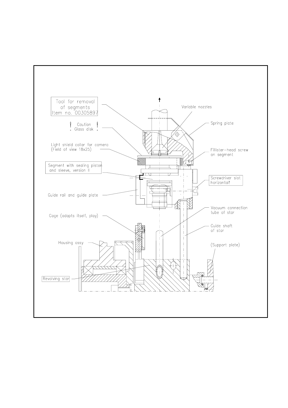
Carefully remove the segment in the top position with the correct segment removal tool , as shown in Fig.
9.5.12.
Note: This tool exists in 2 versions. For the segments with sealing piston version 2 you will need the tool
with the Item No. 00305897-02.
NOTE
If "Segment number X" is displayed on the screen, this always stands for "Star position number X". In the
ideal case the segment number (1-12) corresponds to the star position number (1-12), but after individual
segments have been replaced this may no longer be necessarily the case.
●
For this reason when you remove segments make a note straightaway of the allocation of the star position
number (= number on the screen) from which you removed the segment to the segment number
(= last number of the numerical sequence on the segment body, for example, "12").
NOTE
The star nozzle configuration "ACTUAL" must be reestablished after maintenance work during the place-
ment of a batch in order that the time-optimized placement sequence is once again assured.
Nozzles and segments should not be swapped around. Compliance with this will also make fault location
easier.
SIPLACE 80S/F/G User’s Manual 9 Maintenance
Edition 07/97 from Software Version SR.010.xx 9.5 Revolver Head, Segment Version 2 (New Nozzle Seat)
9 - 61
●
Place each segment immediately after removal carefully into the segment storage case or onto a plastic
foam support during maintenance work.
●
Repeat with "Cycle star" until all segments have been removed this way.
Fig. 9.5.12 Removal and installation of segments with sealing piston version 2 at star station 7 using the removal tool

9 Maintenance SIPLACE 80S/F/G User’s Manual
9.5 Revolver Head, Segment Version 2 (New Nozzle Seat) Edition 07/97 from Software Version SR.010.xx
9 - 62
9.5.10.2 Installation of the Segments
For installation of the segments the light gate is fitted to the housing complete (2 hexagon socket screws M3,
see Fig. 9.5.2) and the light gate flap open.
●
Select under "Cycle star". The star position number located at the top in star station 7 is displayed.
●
Check with the aid of the following illustration whether all preconditions for installation have been fulfilled
with the segment.
This will help you avoid faults later on in your maintenance work.
NOTE
Pay particular attention to the slot position of the eccentric shaft: it is essential that it is positioned horizon-
tally! An incorrect slot position will lead to a fatal error message as the star cannot be cycled further.
The allocation of segment number/nozzle size and star position number must be reestablished after instal-
lation of the segment.
●
Pick up the correct segment (having noted its allocation) carefully with the correct segment removal tool
(see Fig. 9.5.12). Hold the segment by the segment body, not by the incremental or driving disk (cleaned!).
●
Insert the segment at star station 7 carefully into the star (see Fig. 9.5.12) and press the button at the top
end of the tool. This causes the segment to be set down.
●
With "Cycle star" position the next installation location at the removal station.
●
Insert the next allocated segment in the star. Proceed until all 12 segments have been installed.
●
Continue maintenance work as follows. The placement head will remain in the service position.
●
Select from the menu "Star head"
→
"Vacuum test".
NOTE
When the head function "Vacuum test" is selected the "ACTUAL" nozzle configuration" is displayed on the
screen in the form of a table and beside it - after hitting "Return" in each case - the freshly obtained vac-
uum values in % for each star positioning .