00191025-01.pdf - 第421页
9 Maintenance SIPLACE 80S /F/G User’s Manual 9.5 Revolver Head, Segment Version 2 (New Nozzle Seat) Edition 07/97 from Software Version SR.010.xx 9 - 62 9.5.10.2 Inst allation of the Segments For instal lation of the seg…
SIPLACE 80S/F/G User’s Manual 9 Maintenance
Edition 07/97 from Software Version SR.010.xx 9.5 Revolver Head, Segment Version 2 (New Nozzle Seat)
9 - 61
●
Place each segment immediately after removal carefully into the segment storage case or onto a plastic
foam support during maintenance work.
●
Repeat with "Cycle star" until all segments have been removed this way.
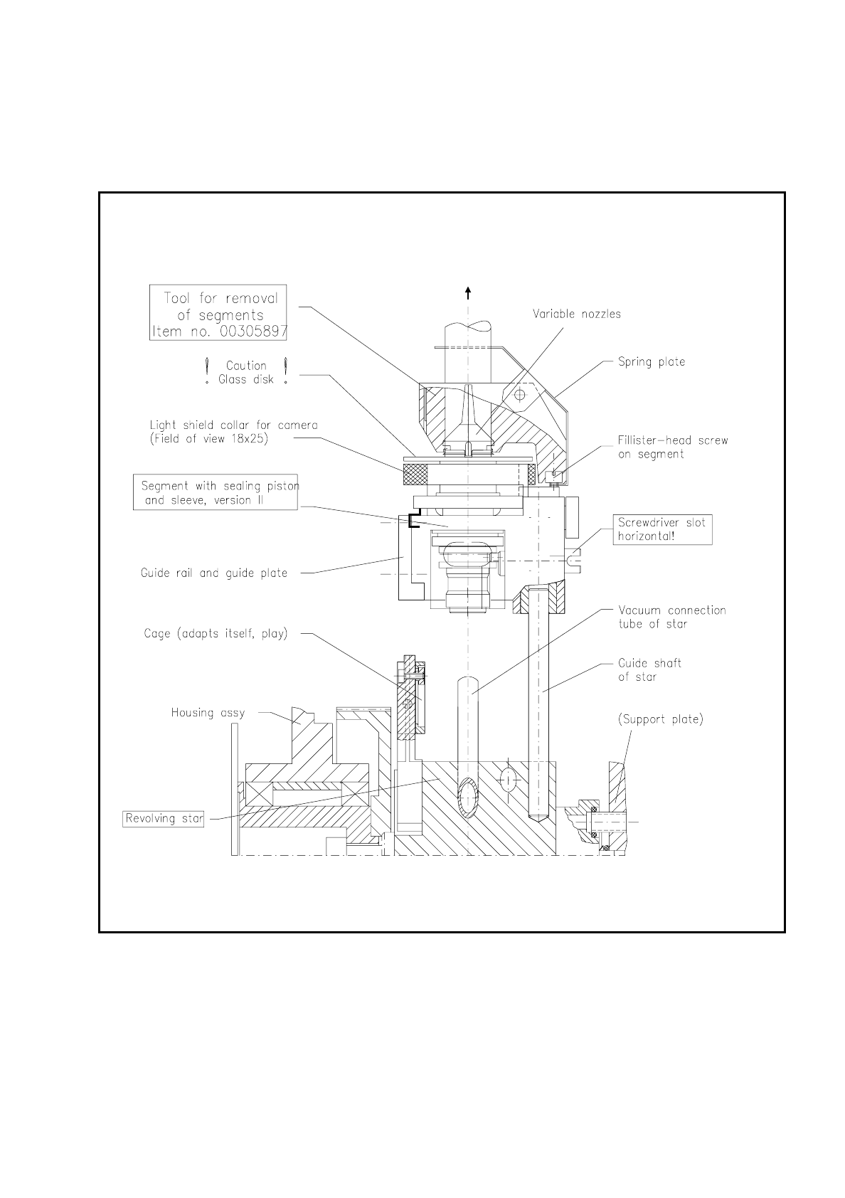
Fig. 9.5.12 Removal and installation of segments with sealing piston version 2 at star station 7 using the removal tool

9 Maintenance SIPLACE 80S/F/G User’s Manual
9.5 Revolver Head, Segment Version 2 (New Nozzle Seat) Edition 07/97 from Software Version SR.010.xx
9 - 62
9.5.10.2 Installation of the Segments
For installation of the segments the light gate is fitted to the housing complete (2 hexagon socket screws M3,
see Fig. 9.5.2) and the light gate flap open.
●
Select under "Cycle star". The star position number located at the top in star station 7 is displayed.
●
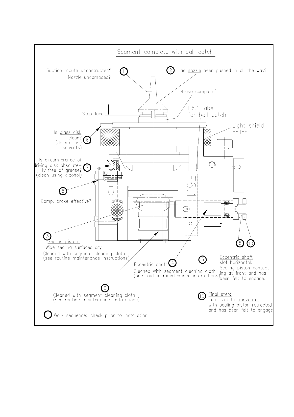
Check with the aid of the following illustration whether all preconditions for installation have been fulfilled
with the segment.
This will help you avoid faults later on in your maintenance work.
NOTE
Pay particular attention to the slot position of the eccentric shaft: it is essential that it is positioned horizon-
tally! An incorrect slot position will lead to a fatal error message as the star cannot be cycled further.
The allocation of segment number/nozzle size and star position number must be reestablished after instal-
lation of the segment.
●
Pick up the correct segment (having noted its allocation) carefully with the correct segment removal tool
(see Fig. 9.5.12). Hold the segment by the segment body, not by the incremental or driving disk (cleaned!).
●
Insert the segment at star station 7 carefully into the star (see Fig. 9.5.12) and press the button at the top
end of the tool. This causes the segment to be set down.
●
With "Cycle star" position the next installation location at the removal station.
●
Insert the next allocated segment in the star. Proceed until all 12 segments have been installed.
●
Continue maintenance work as follows. The placement head will remain in the service position.
●
Select from the menu "Star head"
→
"Vacuum test".
NOTE
When the head function "Vacuum test" is selected the "ACTUAL" nozzle configuration" is displayed on the
screen in the form of a table and beside it - after hitting "Return" in each case - the freshly obtained vac-
uum values in % for each star positioning .
SIPLACE 80S/F/G User’s Manual 9 Maintenance
Edition 07/97 from Software Version SR.010.xx 9.5 Revolver Head, Segment Version 2 (New Nozzle Seat)
9 - 63
Fig. 9.5.13 Inspection of segment before installation (a segment with sealing piston version 2 is shown)
●
With "Return" cycle on to the next segment in the removal station (= star station 7).
●
Look and see whether the nozzle size specified on the screen has been installed.