00191025-01.pdf - 第433页
9 Maintenance SIPLACE 80S /F/G User’s Manual 9.6 IC Head (SIPLACE 80F) Edition 07/97 from Software Version SR.010.xx 9 - 74 ● Check to see whethe r the z axis i s in its to p end posi tion and mov e the IC hea d by hand …
SIPLACE 80S/F/G User’s Manual 9 Maintenance
Edition 07/97 from Software Version SR.010.xx 9.6 IC Head (SIPLACE 80F)
9 - 73
9.6 IC Head (SIPLACE 80F)
9.6.1 Preparatory Work
●
Select: Single functions
→
Gantry 1
→
IC head
→
Return nozzle
DANGER
∆
!
∆
!
∆
!
Switch the automatic placement system off at the main switch and disconnect from the power supply.
●
Open the safety hoods / swivel door.
●
Observe the safety instructions for the coplanarity laser module in Section 9.1
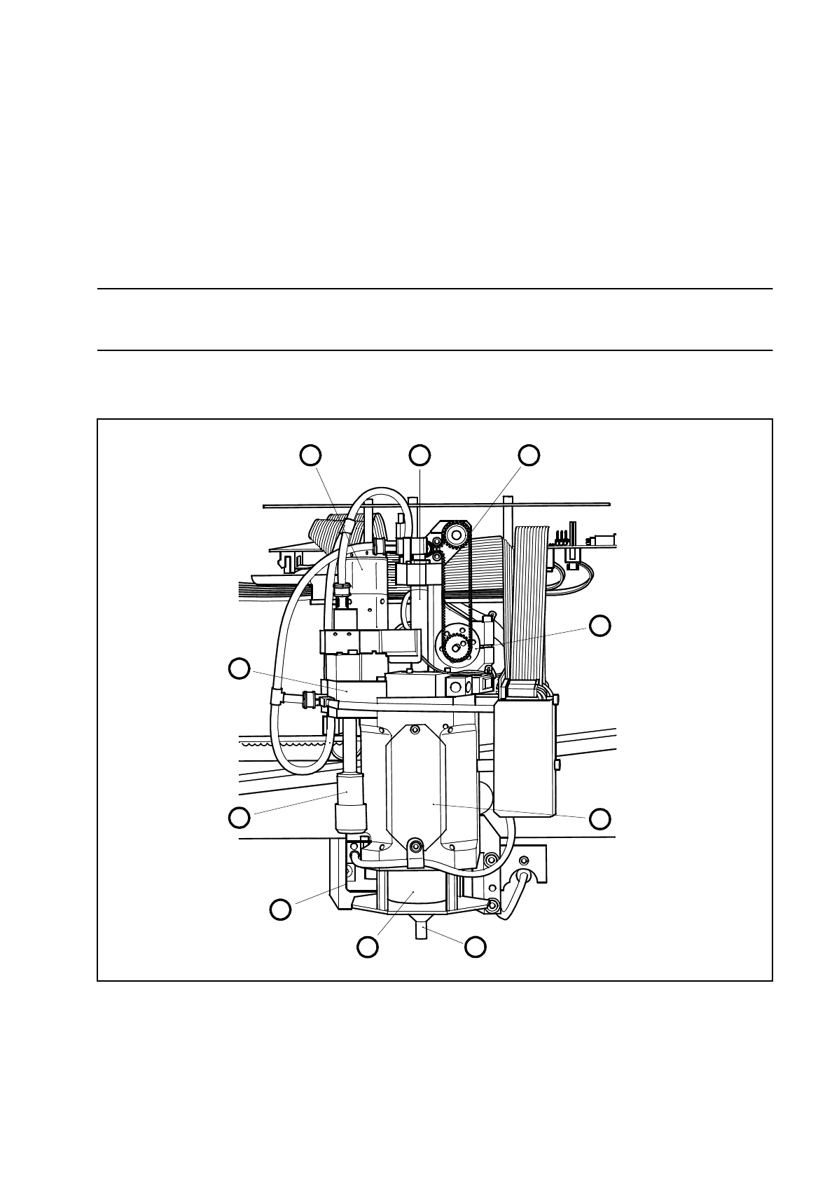
Fig. 9.6.1 Location of the modules requiring maintenance in the IC head
1 Motor/tacho, dr axis 6 Nozzle
2 Venturi nozzle, installed 7 Cover
3 Silencer 8 Motor/tacho, z axis
4 Cover 9 Toothed belt, z axis
5 Encoder flange 10 IC-head sleeve, complete
1 10 9
8
7
65
4
3
2
9 Maintenance SIPLACE 80S/F/G User’s Manual
9.6 IC Head (SIPLACE 80F) Edition 07/97 from Software Version SR.010.xx
9 - 74
●
Check to see whether the z axis is in its top end position and move the IC head by hand to a favorable
working position by pressing on a suitable side of the gantry carriage, thus ensuring that the head does not
get damaged.
Currently when the ’Go to service position’ option in the Gantry functions menu is selected the service
position of the star head will be approached. The IC head service position button will be available at a later
date.
9.6.2 Oiling the Sleeve and Cleaning the Encoder Disk
Carry out maintenance, as shown in Fig. 9.6.2.
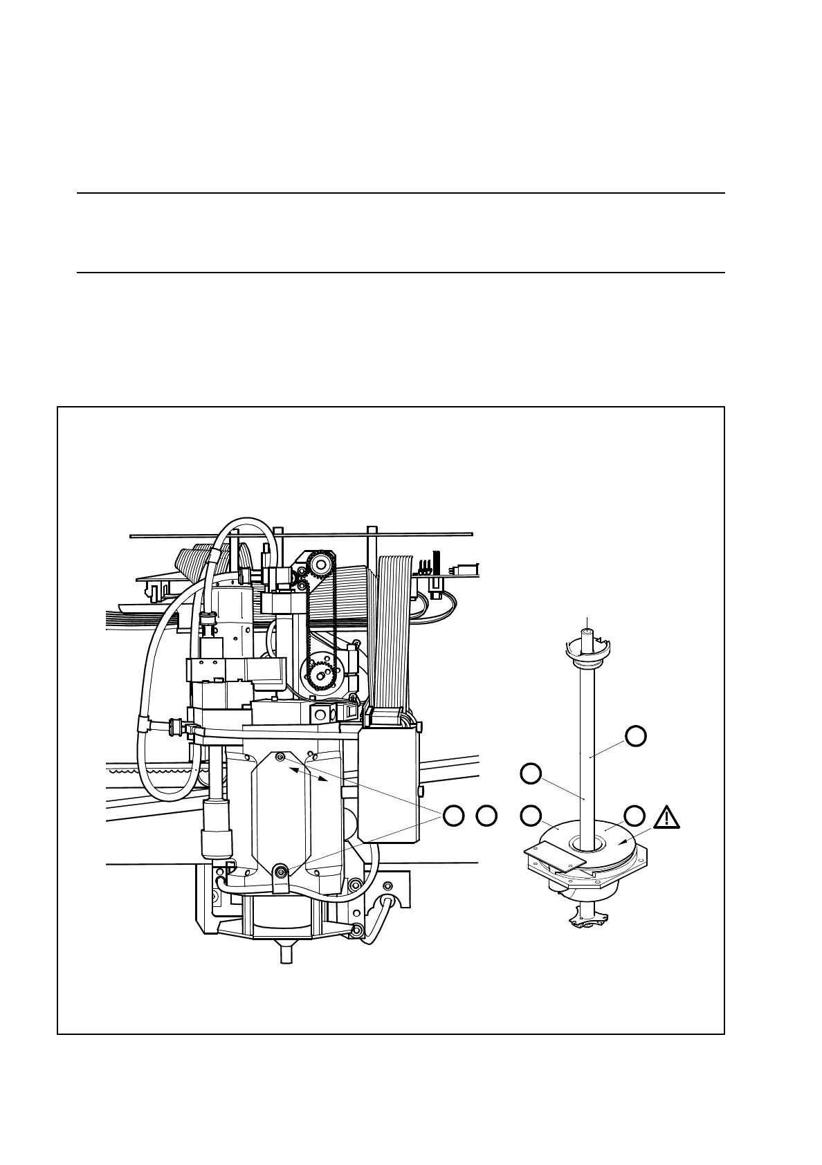
Fig. 9.6.2 Oiling the sleeve and cleaning the encoder disk
A D
,
C
B
2
1

SIPLACE 80S/F/G User’s Manual 9 Maintenance
Edition 07/97 from Software Version SR.010.xx 9.6 IC Head (SIPLACE 80F)
9 - 75
Key to
Fig. 9.6.2
1 Sleeve
2 Encoder disk
Sequence of work in
Fig. 9.6.2
A Undo the M2.5 fillister head screws and remove the cover.
B Rub finest watchmaker’s oil sparingly onto the circumference of the sleeve.
C Clean the encoder disk with a lens cleaning cloth.
D Refit the cover.
∆
!
ATTENTION: Do not get any oil on the encoder disk.
NOTE
You must not slide or rotate the z axis (sleeve) by hand as the clamping device has frictional contact with the
z axis. The oil will distribute itself during placement as a result of the movement of the sleeve.
Do not get any oil on the encoder disk. A dirty encoder disk will result in counting errors or cause errors in
positioning the d axis in the reference position.
●
Remove the cover. Take a clean, lint-free cloth and watchmaker’s oil and apply a thin film of oil to the cir-
cumference of the sleeve.
●
Use proprietary lens cleaning cloths straight from the package (in other words, damp) and after oiling the
sleeve clean thoroughly the entire surface of the encoder disk until the cloth remains clean.
●
To reach all points of the encoder disk, proceed as follows:
Close the safety hoods
→
Switch the machine on and press the start button
→
Call the
Gantry 1 func-
tions
menu. Select
IC head functions
and click on
Turn D axis
. Each time you click on this option the axis
will make a quarter turn (90
°)
.
9.6.3 Maintenance of the Pick-Up Star O-Ring
NOTE
Always select the
Return (nozzle)
function when you want to remove the nozzle from, or insert the nozzle in
the placement head pick-up star. In the first place you will thus avoid damaging the sleeve or nozzle, and in
the second place you will thus ensure that the last current nozzle is registered by the computer as having
been returned. This is necessary if placement is to continue smoothly.
Spare Parts
O-ring 6.5 x 1.6 Viton 80, Item no. 00308445-01
●
If you have complied with the sequence of work described above, the current nozzle will already have been
returned to the nozzle changer. The o-ring is thereby rendered accessible for maintenance work (see Fig.
9.6.3).
●
Remove the o-ring from the annular groove of the pick-up star. Clean both the groove and the o-ring with
alcohol and dry them. If you detect damage, fit a new o-ring.
●
Grease the cleaned or new o-ring sparingly with Unisilkon L250L and put it back in the annular groove
without overstretching the o-ring.
●
Clean the friction wheel of the d-drive unit (Section 9.6.4 from Page 9 - 77).