00191025-01.pdf - 第52页
2 Display and Operating Elem ents SIPLACE 80S/F/G User’s Manual 2.1 Display and Operating Elements Edition 07/97 from Softwareversion SR.010.xx 2 - 4
SIPLACE 80S/F/G User’s Manual 2 Display and Operating Elements
Edition 07/97 from Softwareversion SR.010.xx 2.1 Display and Operating Elements
2 - 3
2.1 Display and Operating Elements
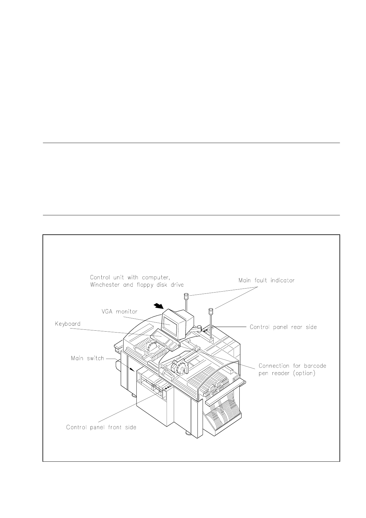
For control purposes each station is provided with its own computer with a Winchester drive, a 3.5" floppy disk
drive, keyboard and VGA color monitor. The computers and drives are accommodated in the control unit of
the machine and should be made accessible solely to correspondingly trained personnel. Two control panels
on the front and back of the machine accommodate the start and stop buttons, the EMERGENCY STOP but-
ton, the key-operated switch and the components counter.
WARNING
∆
!
∆
!
The machine base doors may only be opened by appropriately qualified personnel as certain parts of the
machine have dangerous voltages. Here the applicable accident prevention and VDE regulations must
be strictly complied with.
If these are not observed, the consequences could be serious injury or death or considerable damage to
property.
Fig. 2.1.1 Display and operating elements on the machine

2 Display and Operating Elements SIPLACE 80S/F/G User’s Manual
2.1 Display and Operating Elements Edition 07/97 from Softwareversion SR.010.xx
2 - 4
SIPLACE 80S/F/G User’s Manual 2 Display and Operating Elements
Edition 07/97 from Softwareversion SR.010.xx 2.2 Machine Input and Output Equipment
2 - 5
2.2 Machine Input and Output Equipment
2.2.1 Monitor (DMD 14)
CAUTION
∆
!
●
Protect the monitor from humidity and excessive heat (direct sunlight, heating).
●
Do not obstruct the ventilation louvres.
●
Never attempt to remove the casing as you will then expose yourself to high voltages.
●
Do not spill any liquids over the monitor and not allow any objects to fall through the openings in the
casing.
●
Make sure that the correct operating voltage has been selected.
After the monitor is switched on the station menu appears on the screen in accordance with the privilege level
(password protection). The monitor is switched over by a multiplexer controlled by the machine controller
(MC1). This results firstly in the control menu of the station computer appearing, and secondly the digital
images of the two portal axis systems generated by the PCB and component vision systems can be shown.
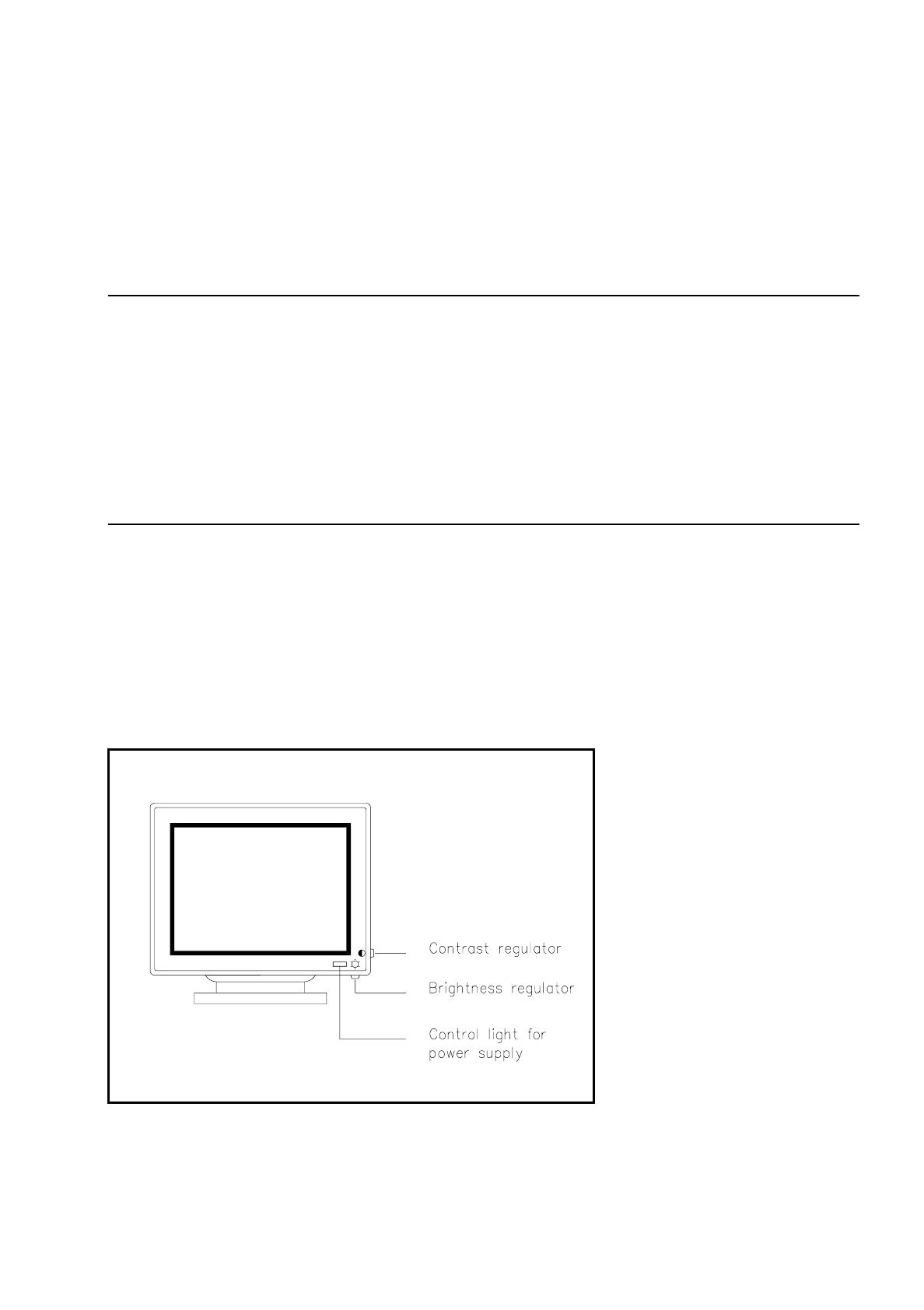
2.2.1.1 Operating and Display Elements on the Front of the Monitor
Fig. 2.2.1 Operating elements and displays on the front side