00191025-01.pdf - 第529页
11 Station Extensions S IPLACE 80S/F/G User’s Manual 11.1 Nozzle-Changer for Revolver Head Edition 07/97 from Software Vers ion SR.010.xx 11 - 4 11.1.2 Technical Data 11.1.2. 1 Software R ecommendat ion Station s oftware…
SIPLACE 80S/F/G User’s Manual 11 Station Extensions
Edition 07/97 from Software Version SR.010.xx 11.1 Nozzle-Changer for Revolver Head
11 - 3
11.1 Nozzle-Changer for Revolver Head
11.1.1 Overview
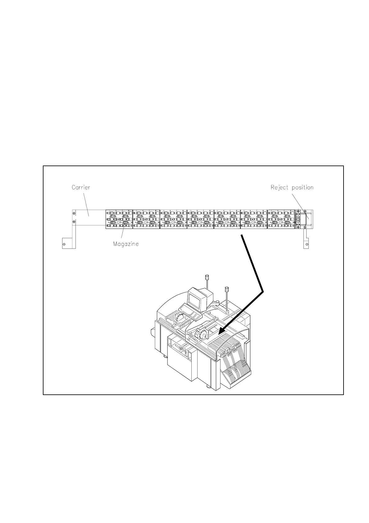
The nozzle-changer is used with the SIPLACE 80S / 80F machines. One nozzle-changer is required per
revolver head. It is modular in design and consists of a minimum of 1 and a maximum of 7 magazines.
Each of these magazines accommodates 12 nozzle garages (see Fig. 11.1.2). The magazines are placed on
a shared support located in the space between the board conveyor and the feeder modules (see Fig. 11.2.1).
The positions of the magazines relative to one another is determined by two setpins.
Fig. 11.1.1 Location of the nozzle changer in the SIPLACE 80S
11 Station Extensions SIPLACE 80S/F/G User’s Manual
11.1 Nozzle-Changer for Revolver Head Edition 07/97 from Software Version SR.010.xx
11 - 4
11.1.2 Technical Data
11.1.2.1 Software Recommendation
Station software Version
≥
008.06
Axis EPROM Version
≥
003.09
SITEST Version
≥
202.003
11.1.3 Method of Functioning
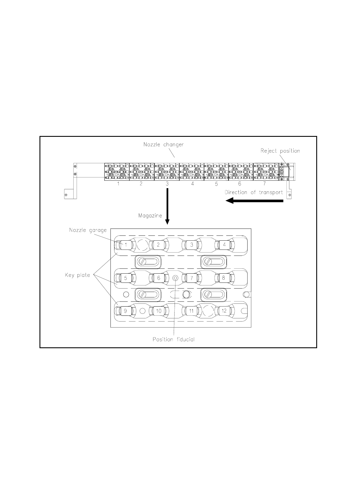
Each individual magazine of the nozzle-changer holds a position fiducial for position recognition.
The individual locations of the magazines are marked with the numbers 1 to 7 on the nozzle-changer. The
individual nozzle garages are continuously numbered from 1 to 12 in the magazines (see Fig. 11.1.2).
NOTE
After consultation with Siemens AUT 5 BSM special magazines can be prepared and will be given a special
coding.
The fixing of the position of the nozzles in the garages takes place via a key plate which can be moved along
an axis by 6 mm. The nozzles will be clamped or released depending on the position of the plate.
The plate is moved by means of a pneumatic cylinder simultaneously for all magazines or all nozzles. All noz-
zles are held or released simultaneously.
If no nozzle change has been carried out, the key plate will always be in the closed position.
Nozzle changer for revolver head
Length 685 mm
Width 60 mm
Height 46 mm
Number of nozzle garages min. 12 / max. 84
Configurable nozzle types 601, 604, 605, 611, 614, 615, 617, 618, 619, 623, 624
Material Vectra and steel
Opening and closing plate < 200 ms
Capacity of rejects container approx. 50 nozzles
Pneumatic system 2 pneumatic supply lines 5.5 and 2.5 bar
Provision tolerance of the individual nozzles
in accordance with measurement
± 0,1 mm
SIPLACE 80S/F/G User’s Manual 11 Station Extensions
Edition 07/97 from Software Version SR.010.xx 11.1 Nozzle-Changer for Revolver Head
11 - 5
●
Picking up a nozzle
-
The z axis of the revolver head moves downwards.
-
The key plate opens.
-
The z axis moves up.
●
Returning a nozzle
-
The key plate opens.
-
The z axis moves downwards.
-
The key plate closes.
-
The z axis moves up.
Fig. 11.1.2 Overview of magazine and nozzle garages
●
Ejecting defective nozzles
-
At ejection position the z axis travels a 14 mm stroke.
-
The z axis moves upward and the nozzle is pulled off the sleeve by a spring wire.