00191025-01.pdf - 第537页
11 Station Extensions SIPLACE 80S/F/G User’s M anual 11.2 Nozzle Changer for IC Head (ICPW20) Edition 07/97 from Software Version S R.010.xx 11 - 12

SIPLACE 80S/F/G User’s Manual 11 Station Extensions
Edition 07/97 from Software Version SR.010.xx 11.2 Nozzle Changer for IC Head (ICPW20)
11 - 11
Each of the individual magazines bears a position marker which is used for position recognition.
The individual locations in the magazines are numbered consecutively from 1 to 4.
The individual nozzle garages in the individual magazines are numbered consecutively from 1 to 5.
The nozzles are held securely in the garages by means of spring-loaded detents. Depending on the direction
in which the IC head axis rotates the nozzles will either be clamped or released.
11.2.4 Notes for the Operator
●
To insert or change nozzles use the nozzle removal tool (see Section 9.6.6.1 in this user's manual).
●
Clean the nozzle changer in the manner described in Section 9.3.7 of this user's manual.

11 Station Extensions SIPLACE 80S/F/G User’s Manual
11.2 Nozzle Changer for IC Head (ICPW20) Edition 07/97 from Software Version SR.010.xx
11 - 12
SIPLACE 80S/F/G User’s Manual 11 Station Extensions
Edition 07/97 from Software Version SR.010.xx 11.3 PCB Bar-Code
11 - 13
11.3 PCB Bar-Code
11.3.1 Overview
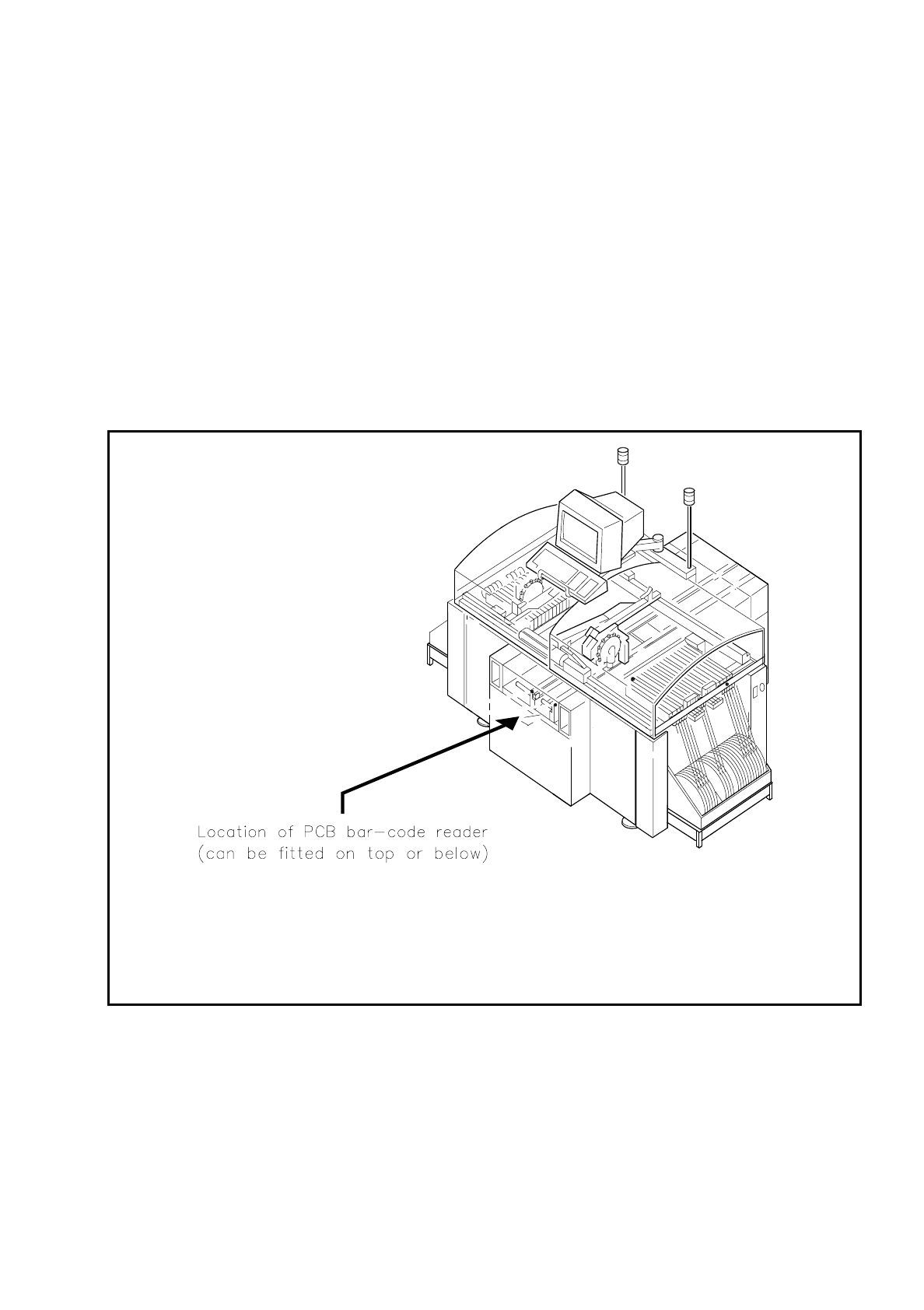
The PCB bar-code can be read from the underside (solder side) or from the top side (insertion side) of a
board.
If the bar code is placed on the top side of a board the reading head will be mounted in such a way that the
reading beam of the bar-code reader hits the board from above.
If the bar code is located on the underside of a board, the reading head will be mounted in such a way that the
reading beam of the bar-code reader hits the board from below.
Fig. 11.3.1 Location where the PCB bar-code reader is installed