00191025-01.pdf - 第539页
11 Station Extensions S IPLACE 80S/F/G User’s Manual 11.3 PCB Bar-Code Edition 07/97 from Software Version S R.010.xx 11 - 14 11.3.2 Notes on Safety CAUTION ∆ ! The readi ng beam of t he bar-cod e reader ha s a radiant p…
SIPLACE 80S/F/G User’s Manual 11 Station Extensions
Edition 07/97 from Software Version SR.010.xx 11.3 PCB Bar-Code
11 - 13
11.3 PCB Bar-Code
11.3.1 Overview
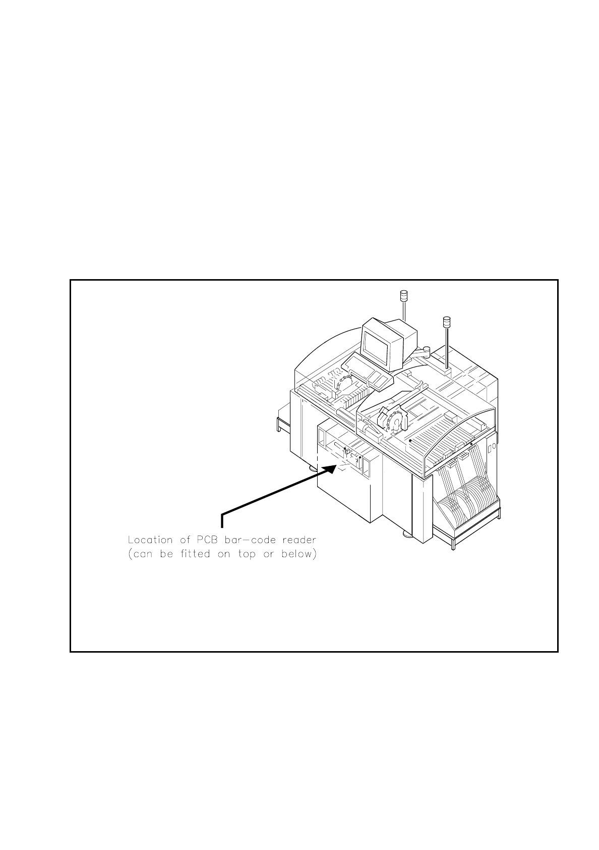
The PCB bar-code can be read from the underside (solder side) or from the top side (insertion side) of a
board.
If the bar code is placed on the top side of a board the reading head will be mounted in such a way that the
reading beam of the bar-code reader hits the board from above.
If the bar code is located on the underside of a board, the reading head will be mounted in such a way that the
reading beam of the bar-code reader hits the board from below.
Fig. 11.3.1 Location where the PCB bar-code reader is installed

11 Station Extensions SIPLACE 80S/F/G User’s Manual
11.3 PCB Bar-Code Edition 07/97 from Software Version SR.010.xx
11 - 14
11.3.2 Notes on Safety
CAUTION
∆
!
The reading beam of the bar-code reader has a radiant power which is less than 1 mW. This means that the
bar-code reader corresponds to laser class 2 and therefore according to DIN EN 60825-1 requires no special
safety devices or guards.
Eyes are protected in addition by the natural reaction of looking away and of closing the eyes.
Beyond this, an electronic safety device ensures that if the polygon wheel is turning too slowly or not at all, the
laser diode will be switched out.
11.3.3 How It Works
The bar-code reader is a reading device which registers and decodes data presented in the form of bar-cod-
ing. The bar-code reader consists of the reading head and the decoder<$IDecoder>.
The laser diode which is built into the reading head creates a beam of monochrome red light. This is focussed
by a lens and deflected by a rotating polygonal mirror wheel. The signals reflected from the bar-coded base
are registered by a photodiode and amplified. This train of electrical impulses which reproduces the sequence
of dark-to-light transitions in the base is then routed to an electronic evaluation device, the decoder.
The decoder consists of two parts: a rapid signal conditioning unit and a processing unit which decodes the
signals and converts them into ASCII format. The data are then routed to a serial interface for further process-
ing.
11.3.4 Parametrization and Adjustment
WARNUNG
∆
!
∆
!
Only personnel trained at the Siemens training center for SMD placement machines is allowed to carry out
parametrization of the bar-code reader.
Before a bar code is actually read, the bar-code reader must know what kind of code is to be read and how
much data information (number of places) is contained in that code. The bar-code reader is furnished with this
information via parametrization. From the structure of the defined code and the number of places it has, the
bar-code reader can then calculate the precise number of lines and blanks.

SIPLACE 80S/F/G User’s Manual 11 Station Extensions
Edition 07/97 from Software Version SR.010.xx 11.3 PCB Bar-Code
11 - 15
NOTE
If you know what bar code you want to process during start-up, the bar code will be set to your bar-code type.
Otherwise the CODE 2/5 interleaved bar-code type will be preinstalled. If you want to change your bar-code
type, the steps you will need to take for parametrization are described below.
Parametrization takes place using the program SR_INST_LPBC.001.001.
The only actions you should carry out in the menues are the ones described below. All other parameters are
standard values and need not be changed.
●
Insert the diskette with the SITEST test program into drive A:>
●
Reboot the system using the key combination Strg (Ctrl)+Alt+Entf (Del)
●
Insert the SR_INST_LPBC.001.001 diskette into drive A:>
●
Reboot the system using the key combination Strg (Ctrl)+Alt+Entf (Del)
●
Switch the control system ON.
●
The set-up menu will be opened.
NOTE
If the set-up menu does not open, there is no communication with the PCB bar-code reader.
Possible cause: +24 V power supply missing, interface disconnected, laser defective.
●
In the Set-up menu select < E >
●
In the Code sub-menu select < 1 >
●
In the Code type sub-menu select < 1>
●
Select the code type you want to work with < Customer-specific>
NOTE
When the code type or number of places is changed both new values will need to be keyed in afresh.
●
Key in the number of places in the bar code <Customer-specific>
Confirm with < Enter >
NOTE
Specify a single number for the number of places in the bar code. If you specify a range of numbers, this
may lead to errors.
●
Quit the menu with < Esc >
●
Quit the menu with < Esc >
●
Quit the menu with < Esc >
●
Secure the parameters with "Store permanent" < 3 >