00191025-01.pdf - 第549页
11 Station Extensions S IPLACE 80S/F/G User’s Manual 11.5 Flip Chip Vision Module Edition 07/97 from Software Version S R.010.xx 11 - 24 11.5.2 Safety Information concerning the Co mponents Vision Systems in the 80F Mach…
SIPLACE 80S/F/G User’s Manual 11 Station Extensions
Edition 07/97 from Software Version SR.010.xx 11.5 Flip Chip Vision Module
11 - 23
11.5 Flip Chip Vision Module
11.5.1 Overview
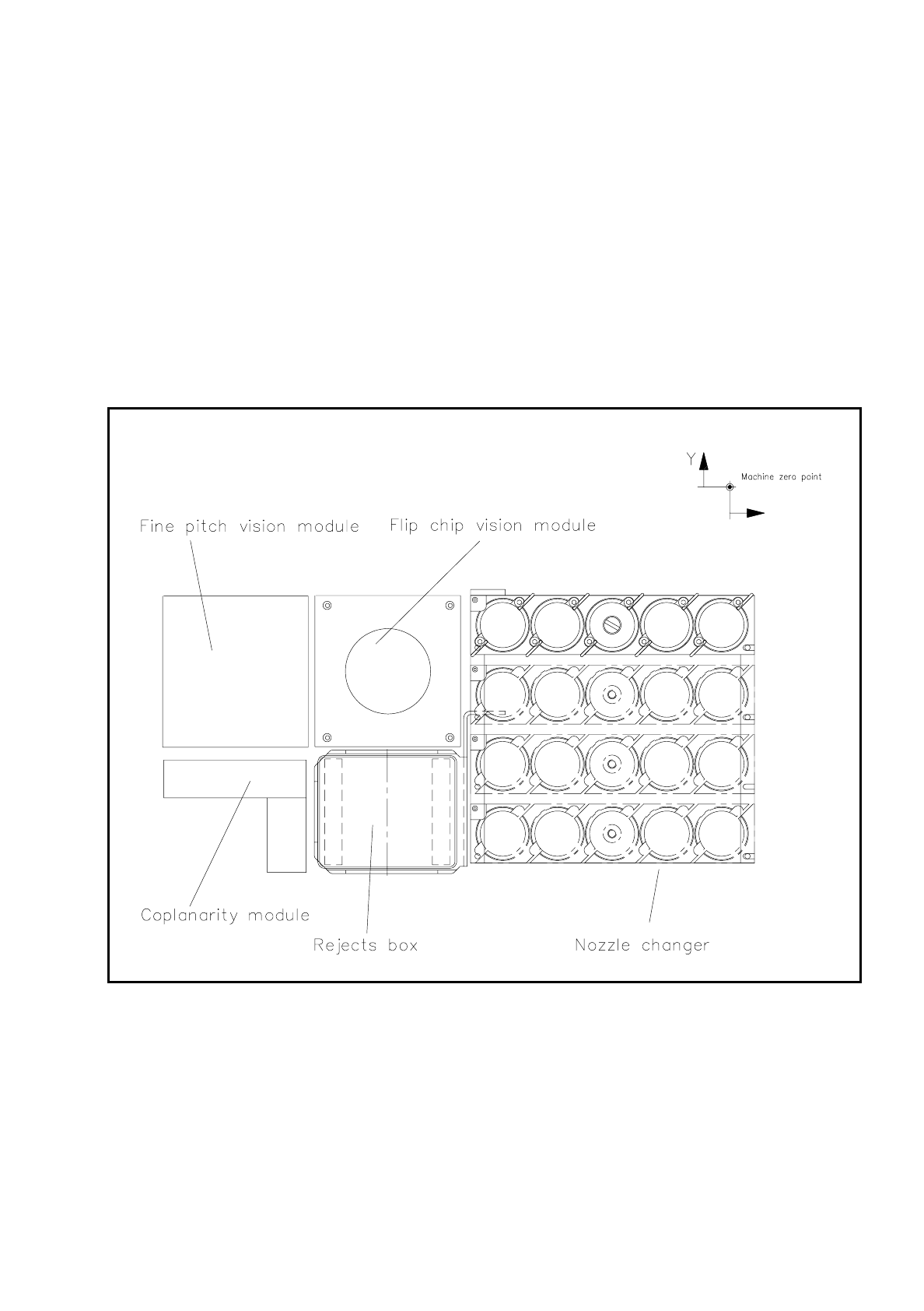
The flip chip vision module is based on the concept of the fine pitch vision system.
It differs from it in that the resolution is higher and the illumination has been modified. Two illumination levels
are available, for a flat and for a middle angle of incidence.
The package form editor has been extended to cover programming of the array-type lead structures and for
some irregular structures.
Fig. 11.5.1 Location of the flip-chip vision module
The module is described, including using it, in Section 7, ’Vision Systems’.

11 Station Extensions SIPLACE 80S/F/G User’s Manual
11.5 Flip Chip Vision Module Edition 07/97 from Software Version SR.010.xx
11 - 24
11.5.2 Safety Information concerning the Components Vision Systems
in the 80F Machine
DANGER
∆
!
∆
!
∆
!
You must not modify or tamper with the safety devices of the 80F machine or of the IC or flip chip module in
any way at all!
The optical radiation of the IC and flip chip sensors corresponds to laser class 1 provided the sensors are per-
manently installed in the machine (EN 60825-1 and IEC 825).
Fig. 11.5.2 Identification label for Laser class 1
LASER CLASS1

SIPLACE 80S/F/G User’s Manual 11 Station Extensions
Edition 07/97 from Software Version SR.010.xx 11.6 Ceramic Substrate Centering
11 - 25
11.6 Ceramic Substrate Centering
11.6.1 General
Ceramic substrate centering is used for holding ceramic substrates securely in the x and y directions and with
the material being protected. Ceramic substrates can also be mounted right up to the edge of the substrate.
11.6.2 Changing from Ceramic Substrate to Board
●
Disconnect the pneumatic line and the electrical connecting line (see item 1 in Fig. 11.6.1).
●
Remove the ceramic substrate centering device (see item 2 in Fig. 11.6.1).
●
Remove the base of the ceramic substrate centering device (see item 3 in Fig. 11.6.2).
●
Remove the three clamping devices (see item 4 in Fig. 11.6.1), fitting the standard guide in their place.
●
Fit the retainer brackets (see item 5a and 5b in Fig. 11.6.1).
●
Set the size of the board (see item 6 in Fig. 11.6.1).
●
For operation under "Single functions" see also Section 6.4 "Transport Functions 80S" of this user's man-
ual.
11.6.3 Maintenance
-
The spherical rotating guide in the x centering unit must be cleaned and lubricated.
-
When necessary, check the pneumatic drive for ease of running.
-
Carry out maintenance of the conveyor as described in Section 9.3.2 PCB Handling.