00191025-01.pdf - 第55页
SIPLACE 80S/F/G User’s Manual 2 Display and Operati ng Elements Edition 07/97 from S oftwareversion SR.010.xx 2.2 Machine Input and Output Equipment 2 - 7 NOTE Horizo ntal and vertic al deflection hav e been adjusted in …
2 Display and Operating Elements SIPLACE 80S/F/G User’s Manual
2.2 Machine Input and Output Equipment Edition 07/97 from Softwareversion SR.010.xx
2 - 6
●
MAINS VOLTAGE ON/OFF
This indicator lights up when the mains voltage supply is connected correctly and the mains switch is
switched on.
●
Brightness
The brightness of the screen can be adjusted using this regulator.
●
Contrast
The contrast of the screen can be adjusted using this regulator.
NOTE
Do not set the brightness or contrast to the maximum. This will unnecessarily shorten the life of the screen.
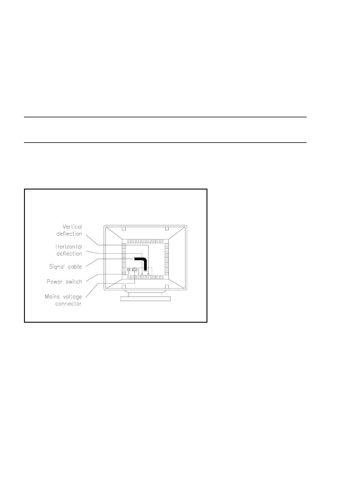
2.2.1.2 Operating Elements at the Back of the Monitor
Fig. 2.2.2 Operating elements on the rear side
●
Power Switch ON/OFF
This toggle switch is used to switch the monitor on or off.
●
Horizontal Deflection
This rotary knob is used for adjusting the horizontal deflection of the screen display.
●
Vertical Deflection
This rotary knob is used for adjusting the vertical deflection of the screen display.
●
Mains voltage connection
First connect the mains cable to the monitor, and then to the socket with earth connection.
SIPLACE 80S/F/G User’s Manual 2 Display and Operating Elements
Edition 07/97 from Softwareversion SR.010.xx 2.2 Machine Input and Output Equipment
2 - 7
NOTE
Horizontal and vertical deflection have been adjusted in the factory and as a rule do not require readjustment.
However readjustment will be necessary in the cases listed below:
• The picture tilts: Adjust the horizontal deflection.
• The picture skips: Adjust the vertical deflection.
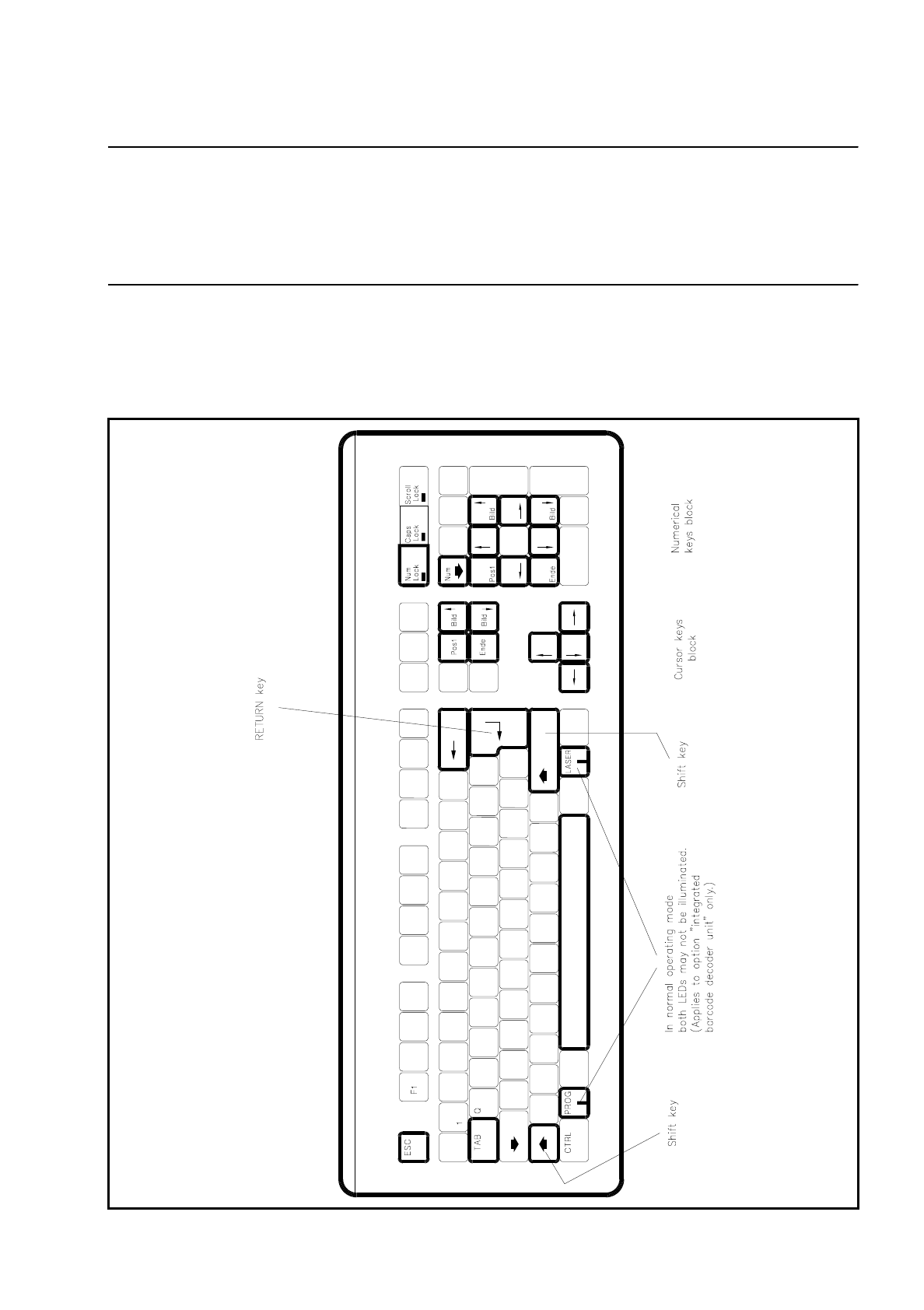
2.2.1.3 Keyboard
The keyboard is an IBM-MF-compatible keyboard with 104 keys and a country-specific configuration (Ger-
man). As an option a barcode decoding unit can be integrated.
Fig. 2.2.3 Keyboard

2 Display and Operating Elements SIPLACE 80S/F/G User’s Manual
2.2 Machine Input and Output Equipment Edition 07/97 from Softwareversion SR.010.xx
2 - 8
It is connected to the computer in the control unit via a stretchable spiral cable with a 5-pin diode plug (DIN).
A connection socket is provided on the righthand side of the keyboard. The keys which are relevant for using
the menus (see Section 2.3) are shown with heavy outlines in Fig. 2.2.3.
NOTE
The keys which are classified under the numerical block,
●
Bild
↑
[PgUp] / Bild
↓
[PgDn]
●
Pos1 [Home]
●
Ende [End]
●
Arrow up / down / left / right,
are only active in these functions when the NUMLOCK function has not been activated (LED not illuminated).
When NumLock is activated this block functions as a keypad for inputting numbers.
If NumLock is active (LED illuminated) then this function can be deactivated simply by pressing the NumLock
key on the numerical keyboard.
On the bottom row of keys on the keyboard two special keys are to be found, marked "LASER” and "PROG”,
each with a built-in LED which lights up when that function has been activated. The key marked "PROG” is
provided for selecting the programming mode of the barcode pen, while the key marked "LASER” allows you
to swap between barcode pen and laser scanner gun.
NOTE
During normal operation make sure that both of these key functions are inactive: neither LED is illuminated.
2.2.1.4 BARCODE Reader Pen (Option)
The barcode reader pen will assist you, particularly under production conditions, to read off data from
component reels rapidly and reliably, in order, for example, to compare component stocks with the quantities
requested by the set-up file (refill check). Successful reading in of each data record is acknowledged by an
acoustic signal.
2.2.1.5 Switches on the Machine
Fig. 2.2.4 shows the location on the machine of the main switch, press buttons for start and stop, the
EMERGENCY STOP button, the key-operated switch and the components counter:
∆
!
∆
!
WARNING
Only appropriately qualified personnel may operate the key-operated switch to deactivate safety functions for
servicing or maintenance work, such as for example traversing the portal axes despite the protective covers
being open and so on. In all other cases the key must be kept safe from unauthorized access, otherwise
serious injuries or damage to the machine may be the result.