00191025-01.pdf - 第571页
17 Nozzle Survey S IPLACE 80S/F/G User’s Manual Edition 07/97 from Software Version S R.010.xx 17 - 2

SIPLACE 80S/F/G User’s Manual 17 Nozzle Survey
Edition 07/97 from Software Version SR.010.xx
17 - 1
17 Nozzle Survey

17 Nozzle Survey SIPLACE 80S/F/G User’s Manual
Edition 07/97 from Software Version SR.010.xx
17 - 2
SIPLACE 80S/F/G User’s Manual 17 Nozzle Survey
Edition 07/97 from Software Version SR.010.xx 17.1 Nozzle Contour Diagrams
17 - 3
17.1 Nozzle Contour Diagrams
In the following section a description is provided of current SIPLACE nozzle contour diagrams. You can use
these diagrams to check whether a specific nozzle is suitable for a particular placement task.
The nozzle contour diagrams provide a way of checking the components height difference and the placement
shadow for each placement task. This way you can determine how close to a plug, for example, a component
can be safely inserted without problems arising.
17.1.1 Definitions
17.1.1.1 Parameters Required
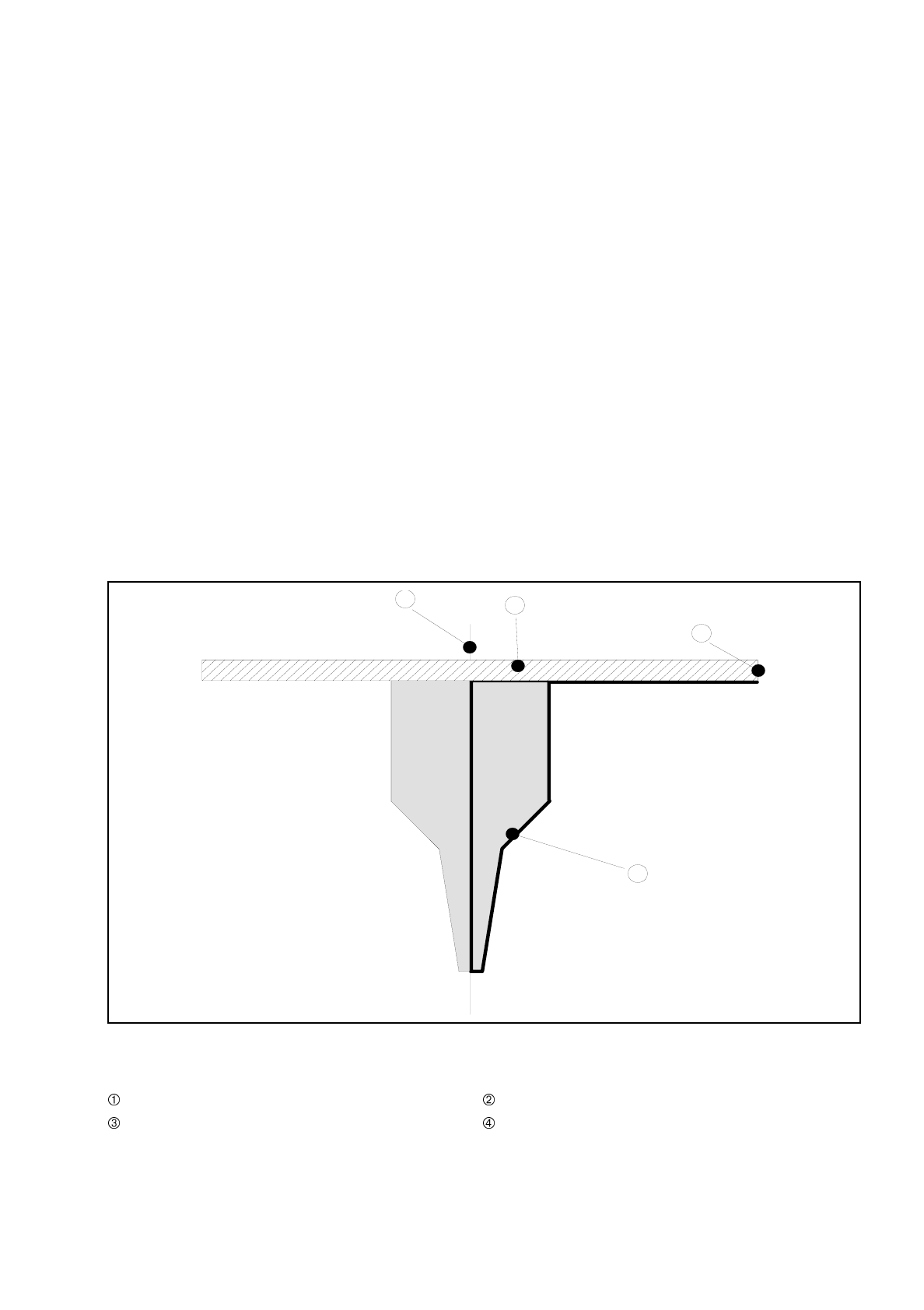
The following parameters will be presented in a nozzle contour diagram (see Fig. 17.1.1 'General view of the
nozzle').
Fig. 17.1.1 General view of the nozzle
- Key to Fig. 17.1.1
Center of nozzle Encoder disk
Outer edge of encoder disk Nozzle contour
3
1
2
4