00191025-01.pdf - 第573页
17 Nozzle Survey SIPLACE 80S /F/G User’s Manual 17.1 Nozzle Contour Diagrams Edition 07/97 from Software Version SR.010.xx 17 - 4 17.1.1.2 Long and Narrow S ides of th e Nozzle For ever y nozzle t ype (for exam ple, 6xx …
SIPLACE 80S/F/G User’s Manual 17 Nozzle Survey
Edition 07/97 from Software Version SR.010.xx 17.1 Nozzle Contour Diagrams
17 - 3
17.1 Nozzle Contour Diagrams
In the following section a description is provided of current SIPLACE nozzle contour diagrams. You can use
these diagrams to check whether a specific nozzle is suitable for a particular placement task.
The nozzle contour diagrams provide a way of checking the components height difference and the placement
shadow for each placement task. This way you can determine how close to a plug, for example, a component
can be safely inserted without problems arising.
17.1.1 Definitions
17.1.1.1 Parameters Required
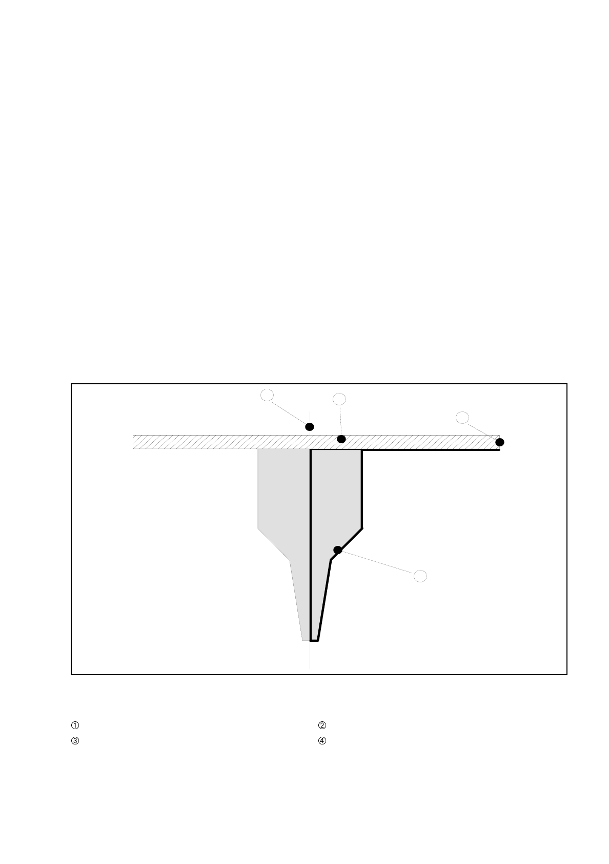
The following parameters will be presented in a nozzle contour diagram (see Fig. 17.1.1 'General view of the
nozzle').
Fig. 17.1.1 General view of the nozzle
- Key to Fig. 17.1.1
Center of nozzle Encoder disk
Outer edge of encoder disk Nozzle contour
3
1
2
4
17 Nozzle Survey SIPLACE 80S/F/G User’s Manual
17.1 Nozzle Contour Diagrams Edition 07/97 from Software Version SR.010.xx
17 - 4
17.1.1.2 Long and Narrow Sides of the Nozzle
For every nozzle type (for example, 6xx) there are two nozzle contour diagrams. One diagram for the long side
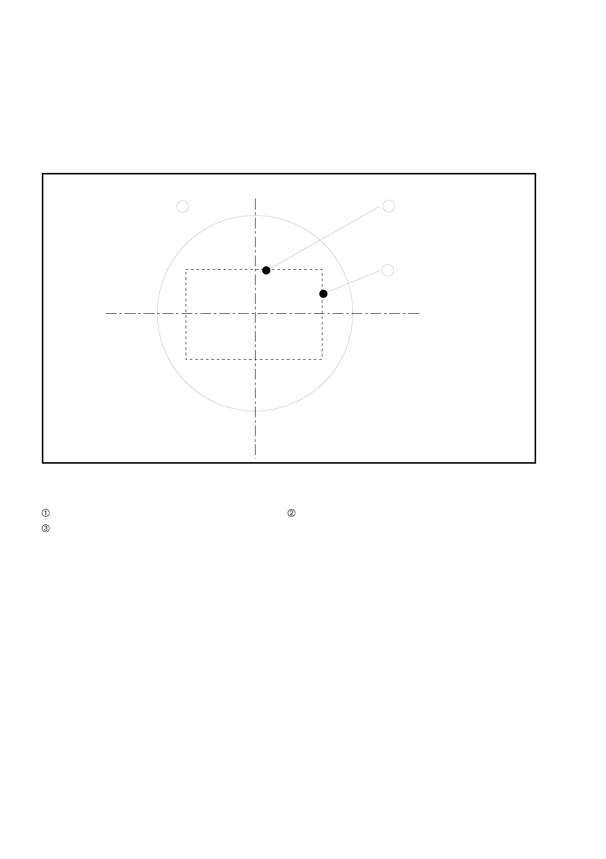
and one diagram for the narrow side of the nozzles. A general view of the nozzle side in question is provided
in Fig. 17.1.2 'Top view of the nozzle'.
Fig. 17.1.2 Top view of the nozzle
- Key to Fig. 17.1.2
Top view of the nozzle Long side of the nozzle
Narrow side of the nozzle
17.1.1.3 Nozzle and Nozzle Contour
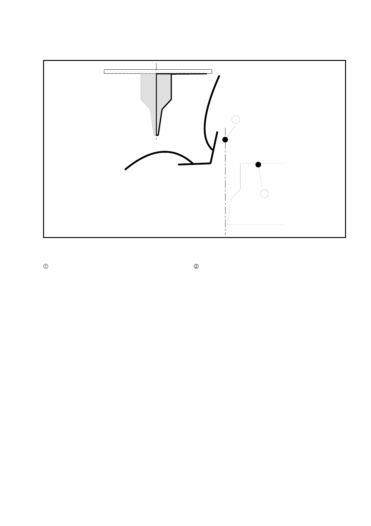
Fig. 17.1.3 'Representation of the nozzle contour (right-hand half of the nozzle)' shows the relation between
the nozzle and the diagram.
The contour of the nozzle is depicted in the nozzle contour diagram.
2
3
1
SIPLACE 80S/F/G User’s Manual 17 Nozzle Survey
Edition 07/97 from Software Version SR.010.xx 17.1 Nozzle Contour Diagrams
17 - 5
Fig. 17.1.3 Representation of the nozzle contour (right-hand half of the nozzle)
- Key to Fig. 17.1.3
Center of the nozzle Nozzle contour
1
2