00191025-01.pdf - 第70页
3 Switching On SIPLACE 80S /F/G User’s Manual 3.1 Introduction: Switching On Edition 12/96 from Software Vers ion SR.009.xx 3 - 4 Fig. 3.1.1 Flow diagram: switching on Without line com puter: input se t-up and c luster D…

SIPLACE 80S/F/G User’s Manual 3 Switching On
Edition 12/96 from Software Version SR.009.xx 3.1 Introduction: Switching On
3 - 3
3.1 Introduction: Switching On
3.1.1 General
The switching-on functions of the SIPLACE 80S/80F/80G2 are identical. Section 3, "Switching on", of the
user's manual, edition 10/95, for this reason applies to all machine types of the SIPLACE family. When the
particular machine type has additional or different functions the corresponding section will include supplemen-
tary information. Differences can also exist in the software version notice and in the header of the screen
menus. This does not however have any influence on the functions.
If the functions of a machine type are modified or supplemented at a later date Section 3 "Startup" will be
revised accordingly in the corresponding sections.
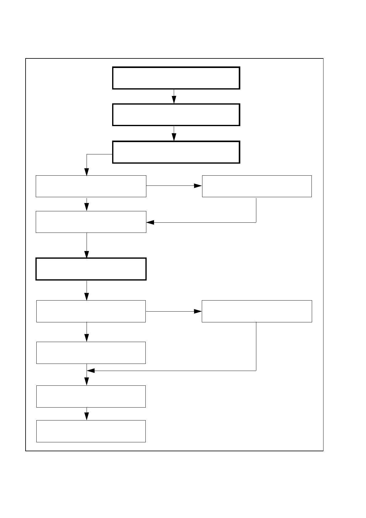
3.1.2 Flow Diagram: Switching On
In the following Figure 3.1.1 the flow diagram for the function "Switching-on" is shown.
3 Switching On SIPLACE 80S/F/G User’s Manual
3.1 Introduction: Switching On Edition 12/96 from Software Version SR.009.xx
3 - 4
Fig. 3.1.1 Flow diagram: switching on
Without
line computer:
input set-up and cluster
Data conversion
if applic. adapt nozzles
With
line computer:
set-up and cluster from LC
Functional sequence
of the reference point run
Press START button
Screen message:
Wait for reference run
If
no
line computer
selection "with" or "without" LC
Station software starts
initialization of the MCs
Start station software
Switch placement machine on
at the main switch
Pre-start check of the placement machine
Placement (Section 5)

SIPLACE 80S/F/G User’s Manual 3 Switching On
Edition 12/96 from Software Version SR.009.xx 3.2 Operator Actions During Switching-On
3 - 5
3.2 Operator Actions During Switching-On
3.2.1 Preconditions for switching on
●
Check whether the power and compressed air supplies of the placement machine are connected.
●
Conduct a visual inspection of the placement machine. Here make sure in particular that there are no
obstacles in the travel range of the gantry axes.
●
Close the protective covers.
●
Make sure that there is
no
system diskette in the floppy drive.
The placement machine may only load the
RMOS
operating system installed on the hard disk.
3.2.2 Switching on
●
Switch on the machine at the main switch.
The placement machine software is loaded (system start). The machine controllers are initialized with the
machine data held on the hard disk.
During initialization of the machine controllers there appears on the screen the following display.
Fig. 3.2.1
SIPLACE 80 V 9.x
Cluster:
Set-up:
Component feeding Display errors
Confirm errors
Machine options
Error
State
Action
:
:
:
Waiting for data