00191025-01.pdf - 第97页
SIPLACE 80S/F/G User’s Manual 5 Placement Edition 12/96 from S oftware Version SR.009.xx 5.5 PCB Handling 5 - 21 5.5 PCB Han dling 5.5.1 PCB Conveyor The print ed circui t board convey or of the SIPLACE 80 p lacemen t ma…

5 Placement SIPLACE 80S/F/G User’s Manual
5.4 Component Handling Edition 12/96 from Software Version SR.009.xx
5 - 20
SIPLACE 80S/F/G User’s Manual 5 Placement
Edition 12/96 from Software Version SR.009.xx 5.5 PCB Handling
5 - 21
5.5 PCB Handling
5.5.1 PCB Conveyor
The printed circuit board conveyor of the SIPLACE 80 placement machine is divided into three zones : the
input conveyor, the center conveyor (placement area) and the output conveyor. Each conveyor zone is fitted
with an ultrasound sensor which detects whether there is a printed circuit board on the conveyor.
In addition, the center conveyor is provided with a built-in printed circuit board stopper which handles the
correct positioning of the board on the center conveyor.
Before placement begins, the printed circuit board is fixed in position on the center conveyor using clamps.
NOTE
When loading the printed circuit board into the machine, the protective covers must be closed or the printed
circuit board will not be clamped in position.
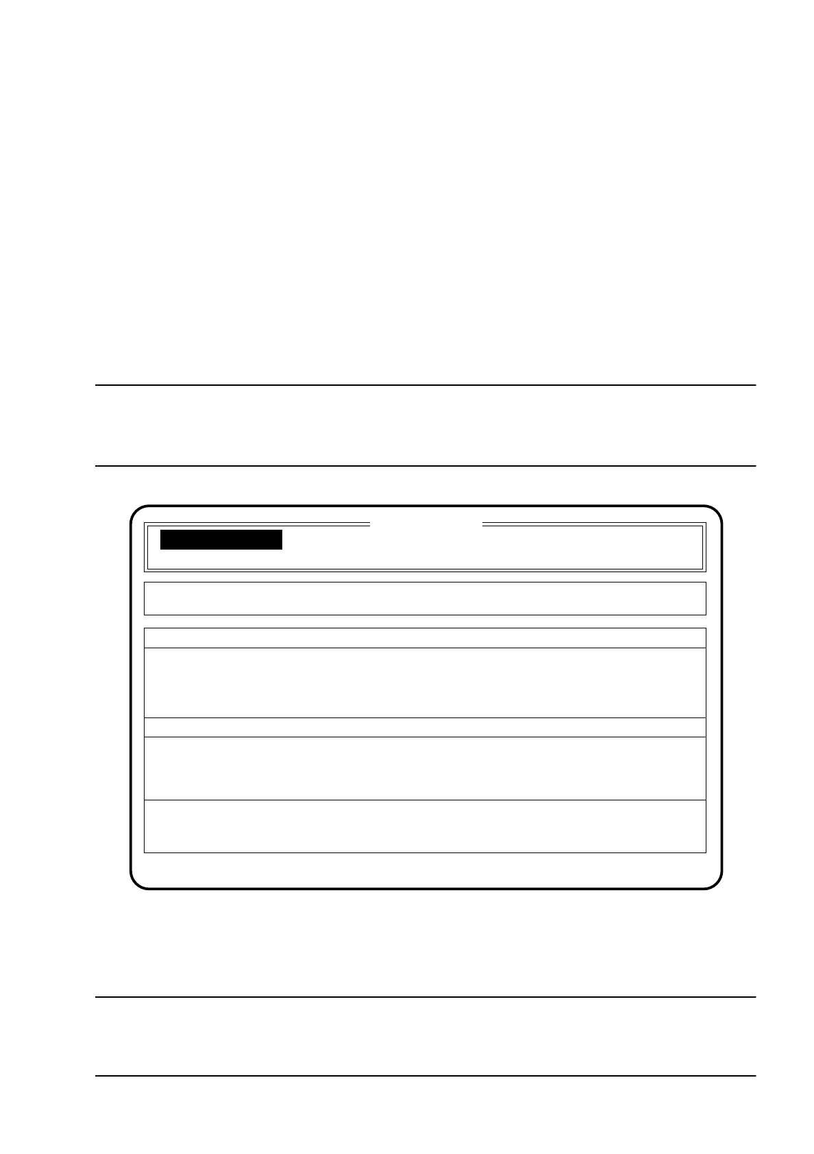
Fig. 5.5.1
●
When the screen message "State: Wait for PCB in input conveyor" requests you to do so, place a printed
circuit board on the input conveyor. Here the printed circuit board must be positioned above the ultrasound
sensor.
CAUTION
∆
!
Do not put your hands inside the traversing range of the portals, DANGER OF INJURY!!
SI 80 V 9.x
Cluster: TEST
Set-up: TEST
Display errors
Confirm errors
Machine options
Error
State
Action
:
:
:
Wait for PCB in input conveyor
Component feeding

5 Placement SIPLACE 80S/F/G User’s Manual
5.5 PCB Handling Edition 12/96 from Software Version SR.009.xx
5 - 22
The printed circuit board is moved automatically onto the center conveyor and placement is started.
After placement has been completed, or aborted (see Section 5.6.8 "Abort Menu") the printed circuit board is
transported onto the output conveyor. Should there already be a printed circuit board on the output conveyor,
the machine waits until the output conveyor is empty.
5.5.2 Interfaces
The SIPLACE 80 placement machine includes two interfaces for communication with the upstream station or
with the input device and the downstream station or output station/oven.
The signals required for the printed circuit board conveyor are transmitted to the machine (to which it is con-
nected) via these interfaces.
The station software enables this interface to be blocked or released after the
line engineer password
has
been entered within the "Machine options" menu.
5.5.3 Printed Circuit Board Position Recognition
The SIPLACE 80 placement machine is equipped with a vision system for optical printed circuit board position
recognition. The fiducials defined in the cluster are approached and measured with the head camera. The
software corrects the placement positions.
The printed circuit board position recognition facility can be enabled or disabled within the "Machine options"
menu after entering the
line engineer password
.
If the position recognition facility is disabled, the position of the printed circuit board is no longer measured.
The placement position is no longer corrected.
If an error occurs during position recognition such as to make continuation of placement impossible, the menu
"Fiducial error" automatically appears on the screen to help in error handling.
This menu is described in more detail in Section 5.6.3 (Fiducial error menu).
NOTE
Editing the fiducials is described in detail in Chapter 7 Vision Systems.
5.5.4 Ink Spot Recognition
The placement machine's vision system, in addition to printed circuit board position recognition, can also be
used to scan ink spots. The ink spot is a defined fiducial on a printed circuit board or individual circuit. This