00198142-01_AI_Stationary-Camera-25-33_TX_de_en - 第70页
Installation Converting the Reject Box 70 Stationary Camera Type 25/33 Stationäre Kamera Typ 25/ 33 Dismantling the sensor ► Dism antle the se nsor (1) on the right NC holder. Dismantling the rear cover ► Remove the thre…
Installation
Converting the Reject Box
Stationary Camera Type 25/33 Stationäre Kamera Typ 25/33 69
3.2
3.2 Converting the Reject Box
Converting the Reject Box
NOTICE
Before installing the camera
It is recommended to convert the reject box before installing the camera.
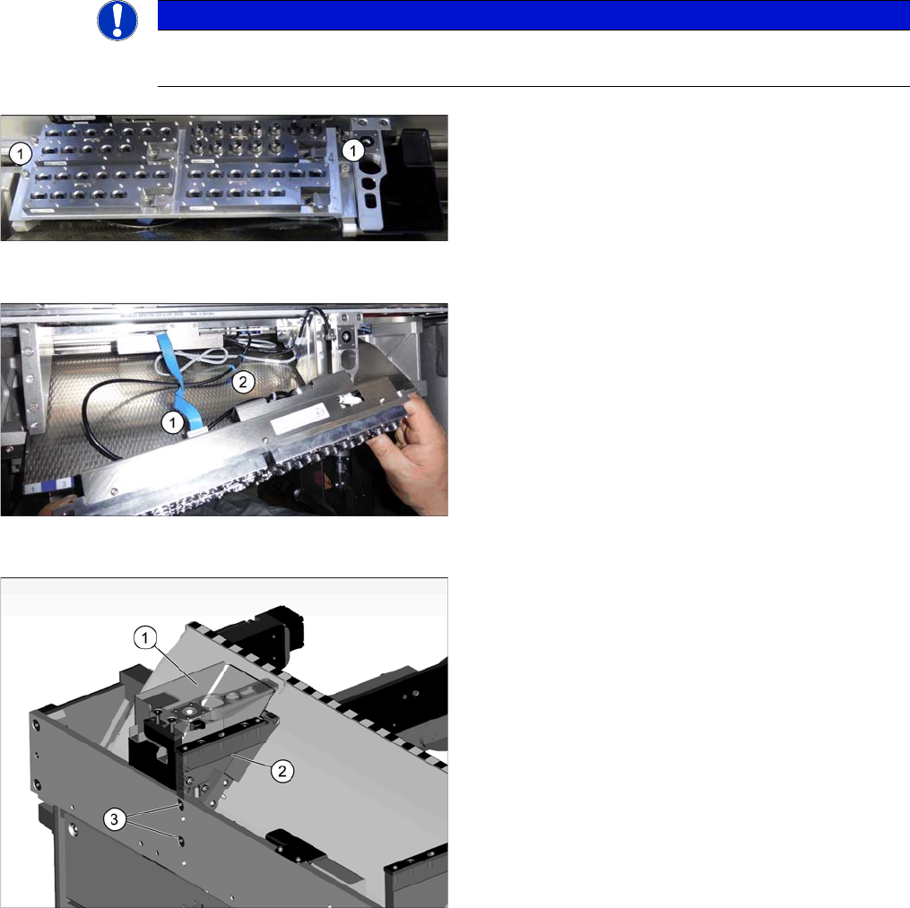
Dismantling NC 1
► Remove the four fixing screws (1) of the nozzle
changer (NC).
Dismantling NC 2
► Unplug the electrical (1) pneumatical connections (2)
of the nozzle changer and put the NC aside.
Dismantling the NC holder
► Remove the reject bin (1).
► Remove the fastening screws (3) of the right NC
holder (2) and lift off the NC holder.
Installation
Converting the Reject Box
70 Stationary Camera Type 25/33 Stationäre Kamera Typ 25/33
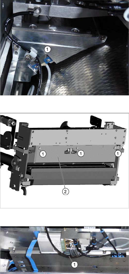
Dismantling the sensor
► Dismantle the sensor (1) on the right NC holder.
Dismantling the rear cover
► Remove the three screws (1) fastening the rear
cover (2).
Move the cover a bit to the side and lift it off. Thus, it is
easier to thread the sensor cable.
Converting the sensor
► Push the sensor through the opening (1) on the front
cover.
Installation
Converting the Reject Box
Stationary Camera Type 25/33 Stationäre Kamera Typ 25/33 71
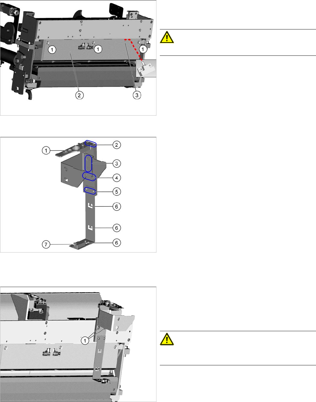
Fitting the rear cover
► Fasten the rear cover (2) with three screws (1).
The sensor cable is run through the opening (3) in the
cover.
CAUTION!
Make sure not clamp any hoses or cables.
Fitting the reject bin holder
1. Nozzle station [03090348
-
xx]
The nozzle station is fitted after measuring the height.
2. Fastening screws of the nozzle station [00333782
-
xx]
3. Fastening screws for retaining bracket ISO10642-
M5x10-A2-70 [03082832
-
xx]
4. Fastening screws of the complete holder on the COT
insert DIN7984-M6x12-A2-70 [03081847
-
xx]
5. Fastening screws ISO 7380-2 M 3 x 6-A2-70
[03099571-xx], only for setting the sensor height
6. Three lugs for cable ties
7. Sensor [03088550
-
xx]
The sensor that is already installed and cabled on the
insert is used.
► Fit the individual parts of the reject bin holder.
► Use the cable ties to fix the sensor to the three lugs.
Fitting the reject bin holder
► Fit the reject bin holder with two fastening screws
DIN7984-M6x12-A2-70 [03081847-xx] (1) on the
COT insert.
Push the sensor cable behind the cover as far as pos
-
sible.
CAUTION!
If too much cable length lies in front of the cover the reject
may damage the cable.