00198142-01_AI_Stationary-Camera-25-33_TX_de_en - 第76页
Installation Fitting the Stationary Camera Type SST25 76 Stationary Camera Type 25/33 Stationäre Kamera Typ 25/ 33 Putting on the Upper Part and Checking the Installation Height NOTE: The uppe r section of the ca mera is…
Installation
Fitting the Stationary Camera Type SST25
Stationary Camera Type 25/33 Stationäre Kamera Typ 25/33 75
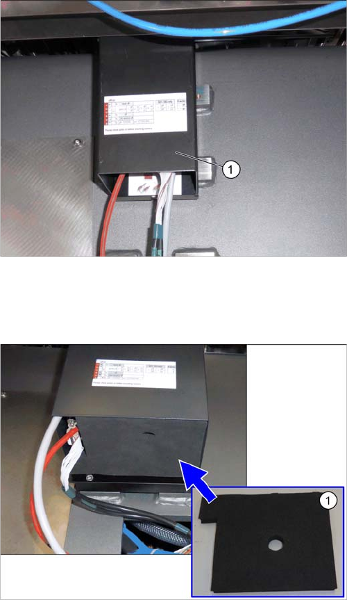
Hooking in the bottom cover
Inserting the Dust Cover
Hooking in the bottom cover
► Hook the bottom cover (1) of the camera in.
Inserting the dust cover (SST33 as example)
► Insert the dust cover made of foam plastic (1) into the
bottom cover.
Installation
Fitting the Stationary Camera Type SST25
76 Stationary Camera Type 25/33 Stationäre Kamera Typ 25/33
Putting on the Upper Part and Checking the Installation Height
NOTE: The upper section of the camera is assigned specifically to the lower section of the camera!
NOTICE
The upper section of the camera is assigned specifically to the lower section of the camera!
The upper section of the camera may not be used with a different bottom section. Both the up
-
per and lower sections are mechanically and electrically coordinated and may not be ex
-
changed for use with other cameras. The serial and version numbers of the top and bottom
sections of the camera must be identical.
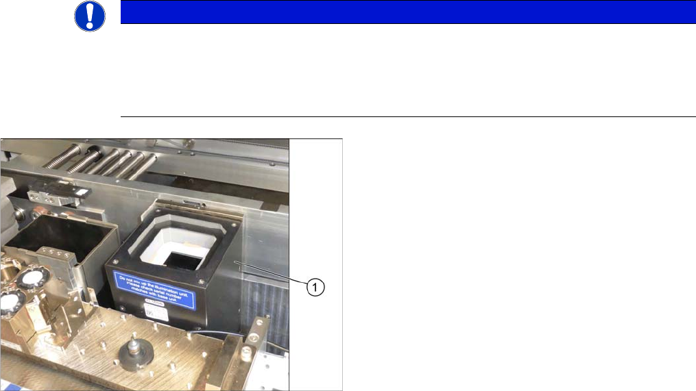
Putting on the Upper Part and Checking the Installation
Height
► Put the upper part (1) on the basic unit.
► Check the installation height. The support plate and
the upper part must be below the top edge of the con
-
veyor rail.
Installation
Fitting the Stationary Camera Type SST33
Stationary Camera Type 25/33 Stationäre Kamera Typ 25/33 77
3.4
3.4 Fitting the Stationary Camera Type SST33
Fitting the Stationary Camera Type SST33
This section describes the installation of a stationary camera of type SST33 GigE.
For installing a stationary camera of type SST25 GigE, refer to section "3.3 Fitting the Stationary Camera
Type SST25" [ ➙ 73].
Setting the DIP Switches
Fitting the Basic Camera Unit
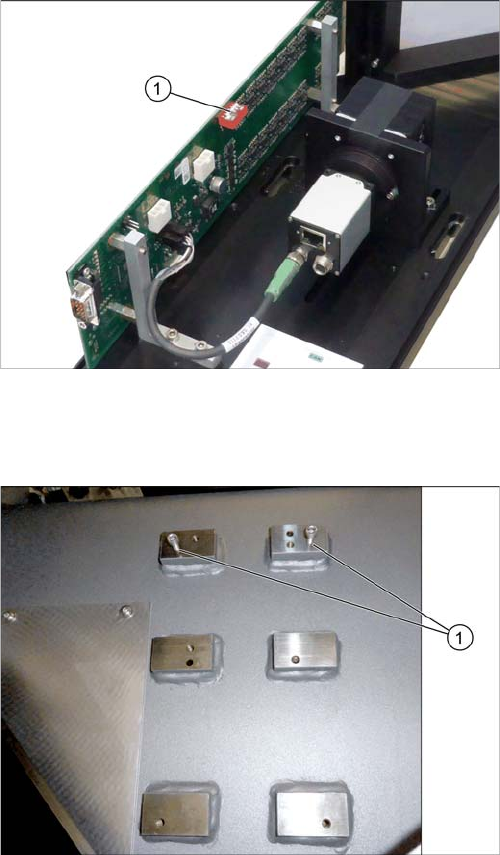
Setting the DIP Switches
► Set the DIP switches (1):
S1.1 to S1.5: OFF
S1.6: ON
(See also "4.2.1.2 Vision LED Controller VLC33 GigE
DTC [03117981-xx]" [ ➙ 88]).
Screwing in the screws
► Loosely screw in the upper screws (1).
(ISO4762-M6x25-A2-70 [03042575
-
xx])
Use the outer bottom screw positions.