00198142-01_AI_Stationary-Camera-25-33_TX_de_en - 第85页
Appendix 4.1.2 Nozzle Changer Setting Excerpts from the Service Manual Stationary Camera Typ e 25/33 Stationäre Kamera Typ 25/33 85 4.1.2.2 4 . 1 . 2 . 2 S e t t in g t h e H e ig h t o f t h e N o z z le S t a t io n Se…
Appendix
Excerpts from the Service Manual 4.1.2 Nozzle Changer Setting
84 Stationary Camera Type 25/33 Stationäre Kamera Typ 25/33
4.1.2
4.1.2 Nozzle Changer Setting
Nozzle Changer Setting
4.1.2.1
4.1.2.1 Setting the Nozzle Changer Height
Setting the Nozzle Changer Height
Parts, Equipment and Tools
▪ Measuring scale
▪ NC shim plate [03021079-xx]
Overview
Setting
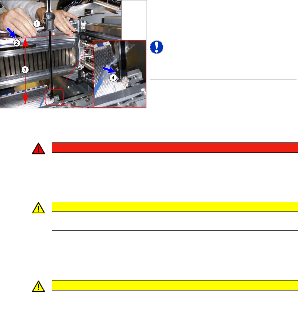
DANGER - Magn ets - Reference t o Safety Chapte r
► During the following inside measurement, make sure that the tip of the measuring scale does not
tough the magnetic strip, as this might scratch it!
► Position the measuring scale (1) on the top edge of the X axis upper linear guide (2) and measure
the distance to the nozzle changer contact surface (4).
► Hold the measuring scale vertically.
► The setting value (3) is 277 +/
-
0.2 mm.
You can adjust the height, where necessary, by removing or adding NC adjusting plates.
► Calibrate the position of the nozzle changer.
Overview of measurement procedure
1. Measuring scale
2. Top edge of the X axis upper linear guide
3. Values to be set (277 +/- 0.2 mm)
4. Nozzle changer contact surface
NOTICE!
Alternatively, you can measure from the top edge of the
lower guide rail of the gantry. In this case, the distance is
116.0+/
-
0.2 mm.
DANGER
Strong permanent magnet fields
Observe the safety instructions in section "1.1.2 Safety Instructions for Working with Strong
Magnetic Fields" [ ➙ 52].
CAUTION
Strong magnetic forces
Place a suitable plastic plate between the magnet and measuring scale, if required.
CAUTION
Crash hazard!
Do not place too many adjusting plates underneath.
Appendix
4.1.2 Nozzle Changer Setting Excerpts from the Service Manual
Stationary Camera Type 25/33 Stationäre Kamera Typ 25/33 85
4.1.2.2
4.1.2.2 Setting the Height of the Nozzle Station
Setting the Height of the Nozzle Station
Parts, Equipment and Tools
▪ Measuring scale
▪ Adjusting plates: support for nozzle reject device [03039514-xx]
Setting
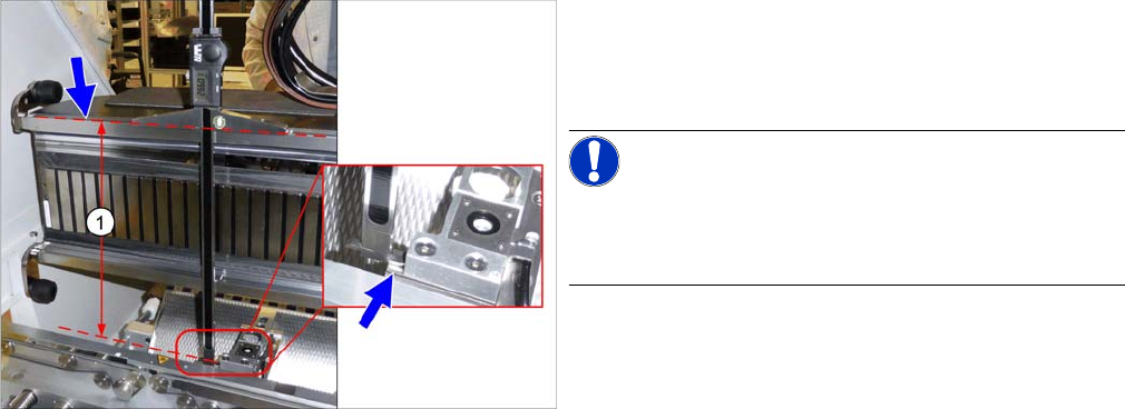
Setting the height of the nozzle station
(taking the standard nozzle station as example)
► The distance (1) between the contact surface of the
nozzle station and the top edge of the upper guide rail
of the gantry needs to be 266.0 +/
-
0.1/-0.3 mm.
You may need to use shim plates to adjust this.
NOTICE!
Alternatively, you can measure from the top edge of the
lower guide rail of the gantry. In this case, the distance is
105.0+/
-
0.1/-0.3 mm.
Appendix
Excerpts from the Service Manual 4.1.2 Nozzle Changer Setting
86 Stationary Camera Type 25/33 Stationäre Kamera Typ 25/33
4.1.2.3
4.1.2.3 Jumpers on the Nozzle Changer
Jumpers on the Nozzle Changer
Overview
Preparation
Setting
► Set the correct value on the jumper for your head type, software and control method.
Nozzle Changer CP20P - Jumper X10
Jumper X10
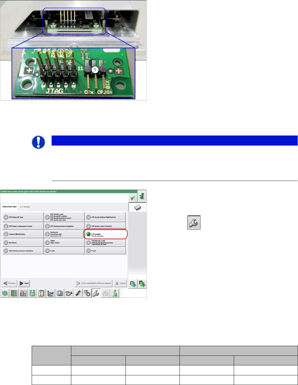
Jumpers on the Nozzle Changer
1. Jumper X10
The jumper X10 needs to be set at the following nozzle
changers:
▪ Nozzle changer basic structure CPx/all assembly -
short [03103649-xx]
▪ Nozzle changer basic structure CPx/all assembly -
long [03103514-xx]
NOTICE
Before installation
Due to the design, this setting must be performed before installation in the machine.
► If the new nozzle changer is being fitted as a spare part in a machine with I/O module con
-
trol, you will need to reconnect the jumper to pin 1-2.
Checking the I/A module control
To check whether the machine has I/O module control,
proceed as follows:
► Switch over to the operator level Service.
► Select the button.
► Select the button Embedded Software.
► Select the button Update Subsystem.
► If I/O module control is present, you will see the entry
Nozzle Changer at I/O Module.
Head SW <= 706.x SW >= 707.x
I/O controller XFCU I/O controller XFCU
CPx, DLM 1-2 1-2 1-2 2-3
C&P20 P --- --- --- 2-3 (factory settings)