192866 Issue 4 - Reel to Reel Manual LoRes - 第15页
TECHNICAL REFERENCE OVERVIEW Chapter Issue 1, Apr 15 Reel to Reel Manual 1.5 1 1. The inner transport vacuum plate moves towards the print station creating the backof f length. 12. The outer transport cla mps, clamp the …

TECHNICAL REFERENCE
OVERVIEW
1.4 Reel to Reel Manual Chapter Issue 1, Apr 15
4. The inner transport vacuum plate moves the product reel away from the print
station, taking up the slack in the product reel (the backoff length).
5. The inner transport clamps release the product reel.
6. The inner transport vacuum plate moves towards the print station.
7. The inner transport clamps, clamp the product reel.
8. The board clamps release the product reel.
9. The inner transport vacuum plate pulls the product reel through the machine
a specified distance to the next product.
10. The board clamps, clamp the product reel.

TECHNICAL REFERENCE
OVERVIEW
Chapter Issue 1, Apr 15 Reel to Reel Manual 1.5
11. The inner transport vacuum plate moves towards the print station creating
the backoff length.
12. The outer transport clamps, clamp the product reel.
13. The rising table moves to vision height.
14. Vision alignment is performed.
15. The rising table moves to print height.
16. The product reel is printed.
TECHNICAL REFERENCE
ELECTRICAL
1.6 Reel to Reel Manual Chapter Issue 1, Apr 15
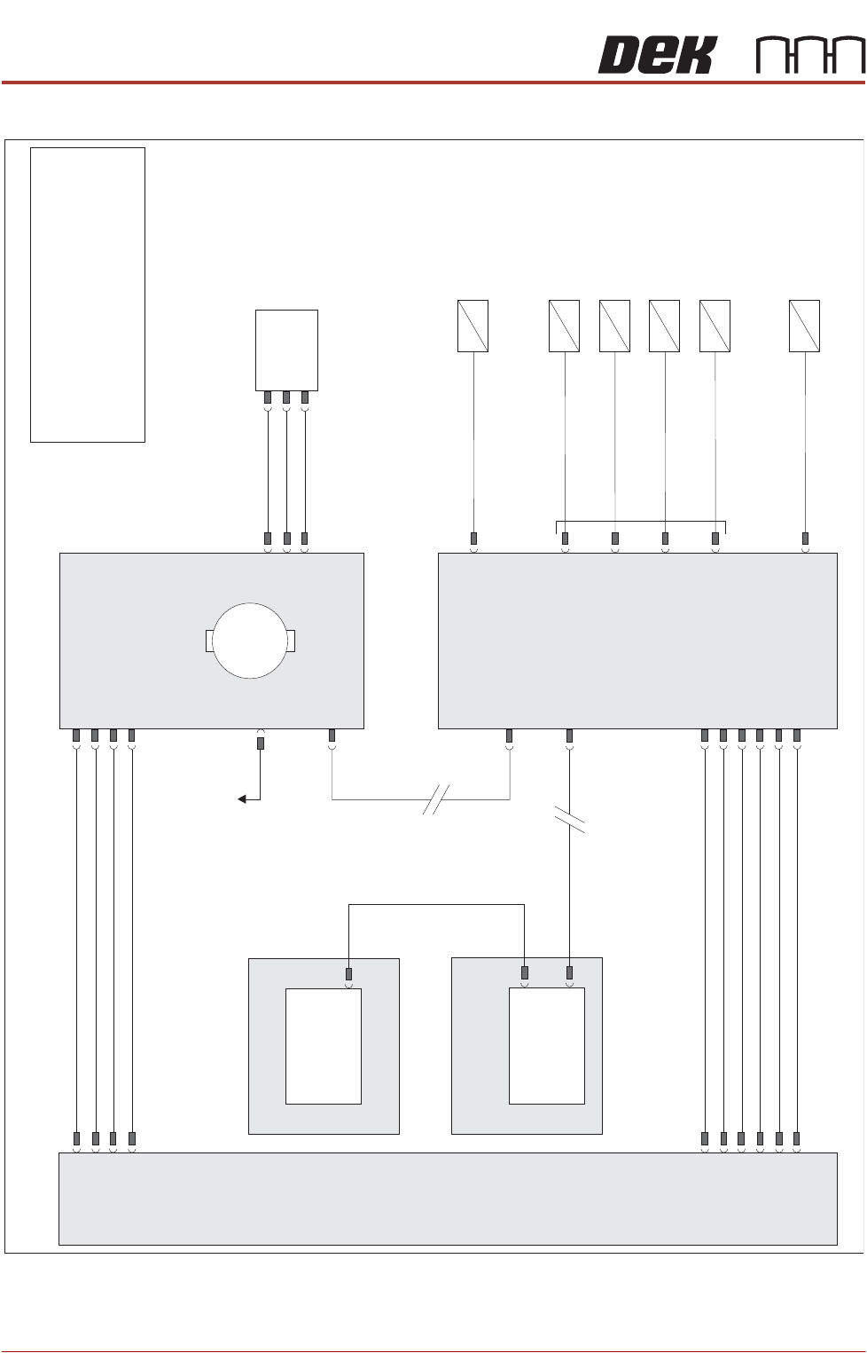
ELECTRICAL
NOTE
For information on the safety interlock switch and lid bolt, refer to the machine’s
Technical Reference manual and Electrical Drawings manual.
Machine P
C
Power
Supply
Enclosure
M37
Motherboard
Machine
Control
Enclosure
M36
NextMove
ES
(I/O Node 1)
X5
Main Machine
I/O Node 2
Board
Clamps
(16SO
L10)
DIG OUT 9
Inner Transport
Clamps (16SO
L14)
DIG OUT 10
Outer Transport
V
ac
Plate (16SO
L22)
Outer Transport
Clamps (16SO
L1
1)
DIG OUT 12
DIG OUT 0
Inner Transport
V
ac
Plate (16SO
L03)
Table Vacuum
(16SO
L12)
DIG OUT 15
DIG OUT 6
N2PL4
N2PL2
N2PL6
CAN Bus
CAN Bus
N2SK2
N11SK3
N11SK2
N2SK1
M37PL15
M37PL4
N2SK3
N11PL4
USB
Transport Mechanism
Home (8SE31)
N11PL1
Transport Mechanism
Servo Motor
I/O Node 1
1
M
To I/O Node 4
42V SW
24V US
24V
0V
0V
0V
0V
Signal
12V
24V US
24V SW
0V
0V
NOTE
The breaks in the CAN Bus chain reflect
that additional I/O Nodes may be fitted,
refer to Machine Control chapter of the
Technical Reference manual for the
complete CAN Bus chain.