192866 Issue 4 - Reel to Reel Manual LoRes - 第17页
TECHNICAL REFERENCE ADJUSTMENTS AND SETTINGS Chapter Issue 1, Apr 15 Reel to Reel Manual 1.7 ADJUSTMENTS AND SETTINGS Rising T able Home Setting W ARNING HOT SURF ACES. THE SURF ACE OF THIS COMPONENT OR SURROUNDING AREA …
TECHNICAL REFERENCE
ELECTRICAL
1.6 Reel to Reel Manual Chapter Issue 1, Apr 15
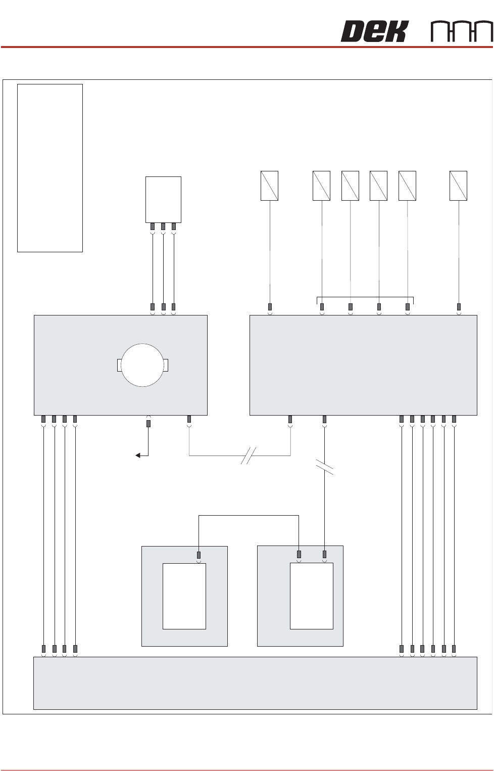
ELECTRICAL
NOTE
For information on the safety interlock switch and lid bolt, refer to the machine’s
Technical Reference manual and Electrical Drawings manual.
Machine P
C
Power
Supply
Enclosure
M37
Motherboard
Machine
Control
Enclosure
M36
NextMove
ES
(I/O Node 1)
X5
Main Machine
I/O Node 2
Board
Clamps
(16SO
L10)
DIG OUT 9
Inner Transport
Clamps (16SO
L14)
DIG OUT 10
Outer Transport
V
ac
Plate (16SO
L22)
Outer Transport
Clamps (16SO
L1
1)
DIG OUT 12
DIG OUT 0
Inner Transport
V
ac
Plate (16SO
L03)
Table Vacuum
(16SO
L12)
DIG OUT 15
DIG OUT 6
N2PL4
N2PL2
N2PL6
CAN Bus
CAN Bus
N2SK2
N11SK3
N11SK2
N2SK1
M37PL15
M37PL4
N2SK3
N11PL4
USB
Transport Mechanism
Home (8SE31)
N11PL1
Transport Mechanism
Servo Motor
I/O Node 1
1
M
To I/O Node 4
42V SW
24V US
24V
0V
0V
0V
0V
Signal
12V
24V US
24V SW
0V
0V
NOTE
The breaks in the CAN Bus chain reflect
that additional I/O Nodes may be fitted,
refer to Machine Control chapter of the
Technical Reference manual for the
complete CAN Bus chain.
TECHNICAL REFERENCE
ADJUSTMENTS AND SETTINGS
Chapter Issue 1, Apr 15 Reel to Reel Manual 1.7
ADJUSTMENTS AND SETTINGS
Rising Table Home Setting
WARNING
HOT SURFACES. THE SURFACE OF THIS COMPONENT OR SURROUNDING
AREA MAY BECOME HOT DURING PROLONGED OPERATION. CARE TO BE
TAKEN WHEN WORKING IN THE VICINITY OF THIS COMPONENT.
1. Remove the screen from the machine.
2. Select Maintenance.
3. Select Diagnostics.
4. Use Next or Previous to highlight Rising Table.
5. Select Select Module.
6. Ensure Home Rising Table is highlighted.
7. Select Run Diagnost.
8. Remove the left hand side safety cover.
9. Open the front printhead cover.
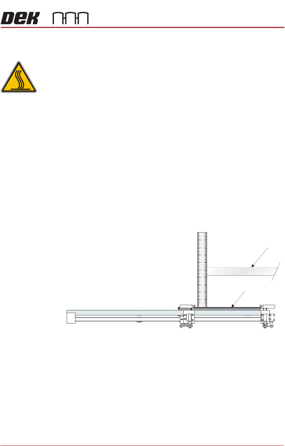
10. Fit the screen so that the rear edge is further forward than the rear edge of
the vacuum top plate.
11. Using a steel rule, measure the distance between the underneath of the
screen frame and the top of the vacuum top plate.
12. Check that the distance is 128mm -0mm/+2mm.
13. If adjustment is not required, remove the steel rule and the screen, close
the front printhead cover and go to Step 22.
Screen
Vacuum Top Plate (Tooling)
View on Left Hand Side of the Rising Table
TECHNICAL REFERENCE
ADJUSTMENTS AND SETTINGS
1.8 Reel to Reel Manual Chapter Issue 1, Apr 15
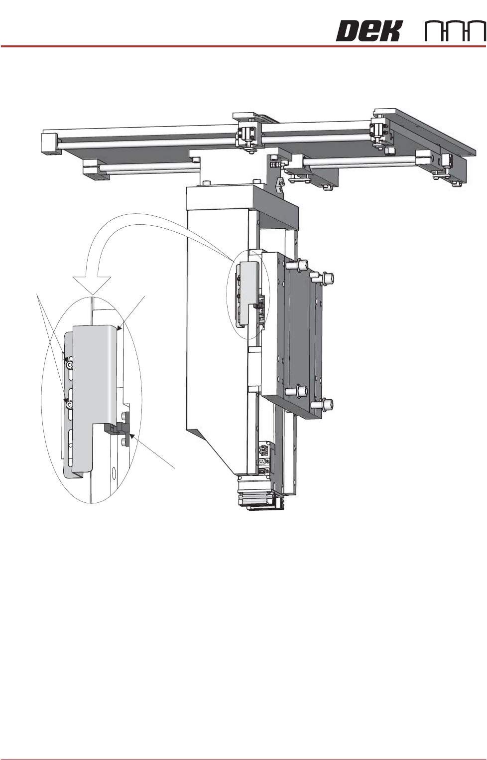
14. From the left hand side of the machine, slacken the two home vane securing
screws.
15. If the rising table needs to be higher, move the home vane downwards and
secure the two home vane securing screws.
16. If the rising table needs to be lower, move the home vane upwards and
secure the two home vane securing screws.
17. Remove the steel rule from the machine.
18. Remove the screen from the machine.
19. Close the front printhead cover.
20. Select Run Diagnost.
21. Repeat Steps 9 to 20.
22. Refit the safety cover.
23. Select Exit.
24. Select Exit.
25. Select Back.
Rising Table
Home Sensor
Rising Table
Home Vane
Vane Securing
Screws